Les Deutsch's Theater Organ Project |
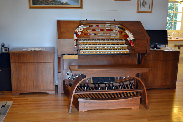
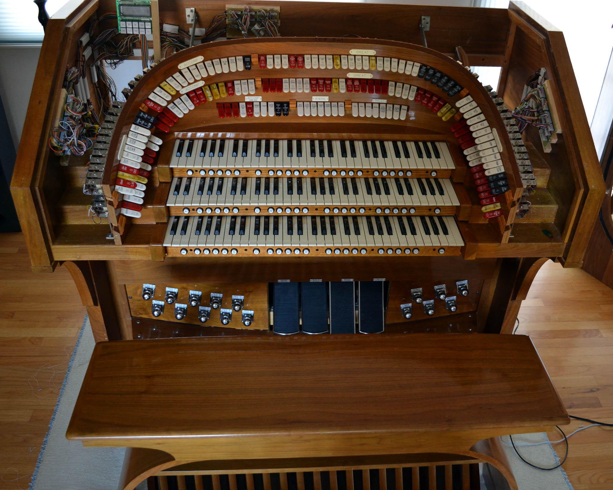
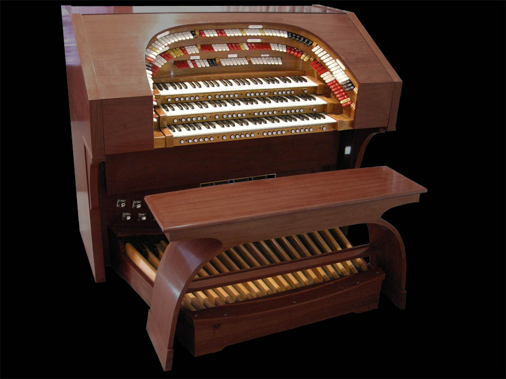
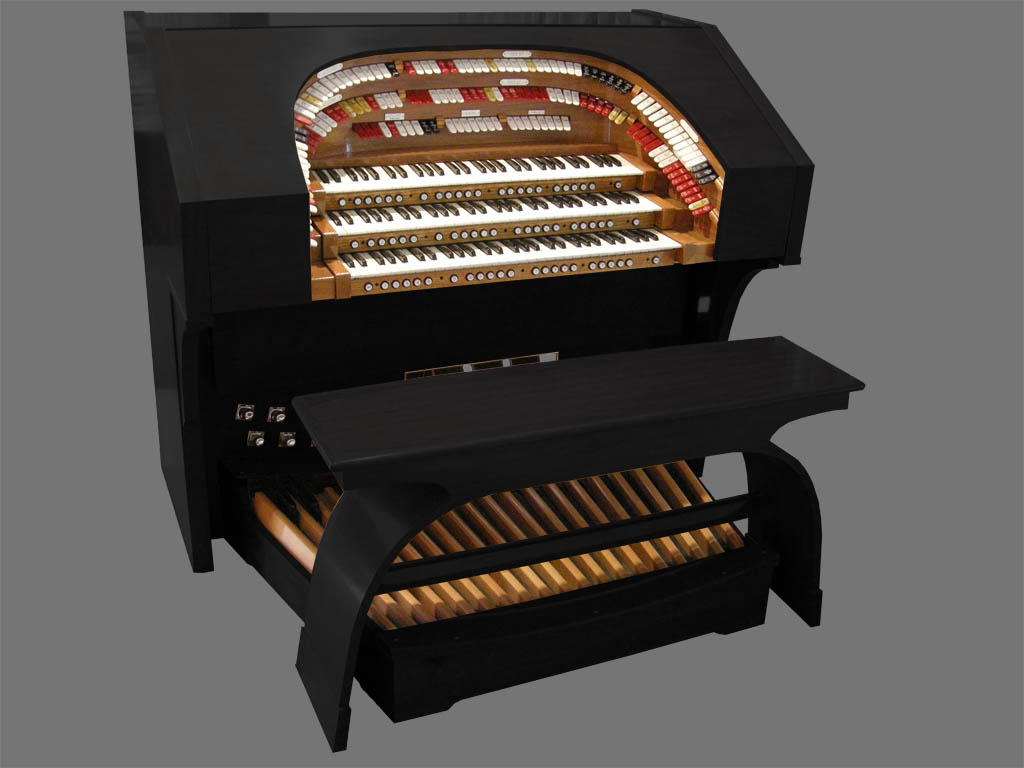
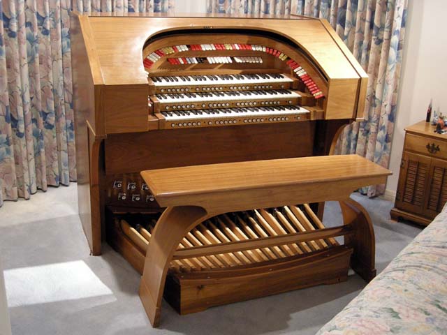
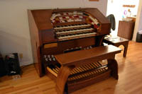
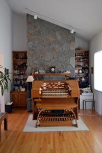
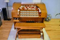
I have been using this page to document my project to convert a very large old analog theater organ to a modern controller console for Hauptwerk and other virtual instruments. The console is now completed as shown here. This page now serves as an historic record of the project.
|
|
|
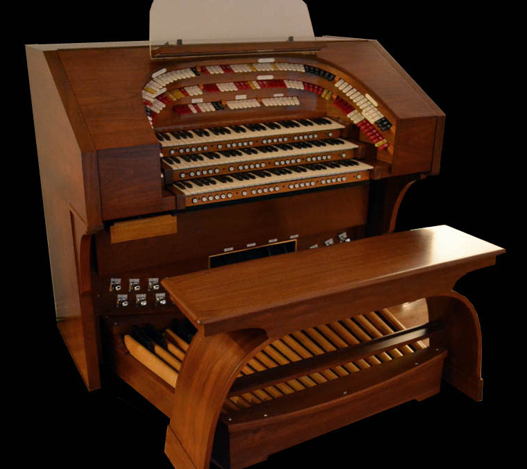
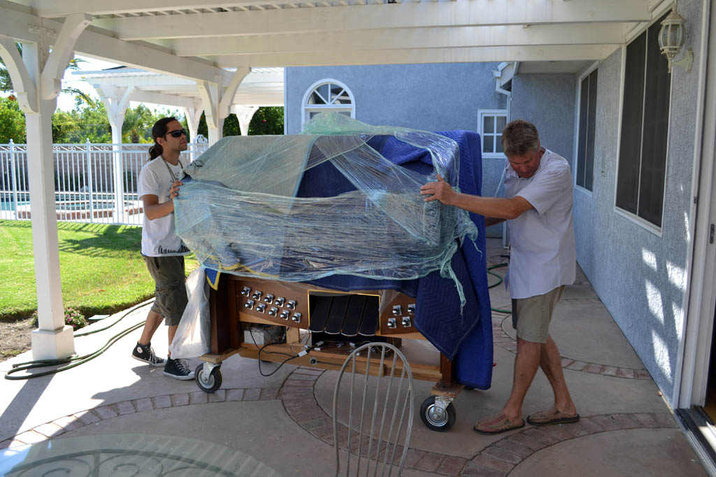
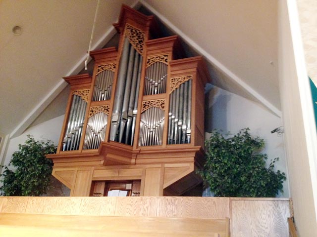
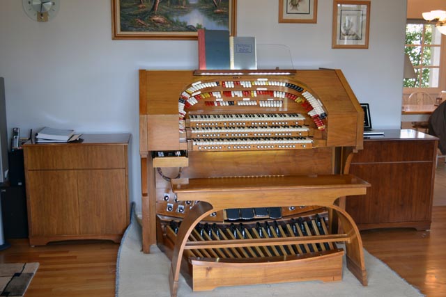
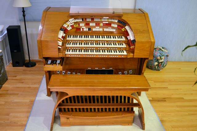
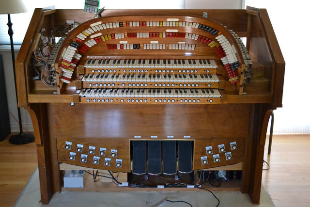
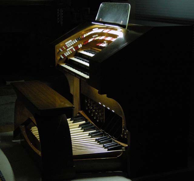
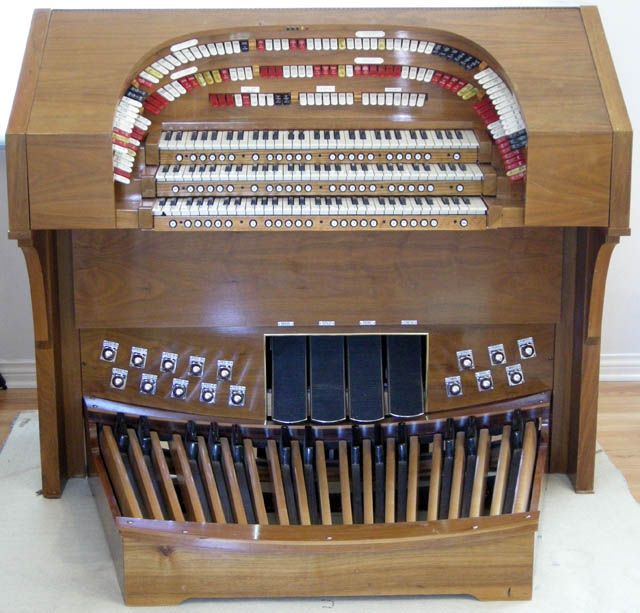
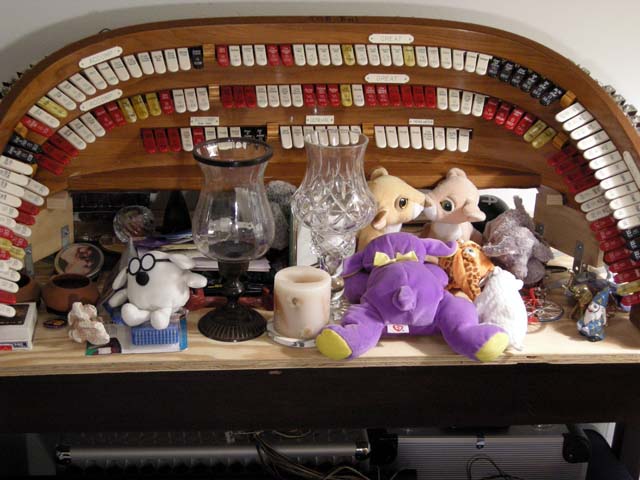
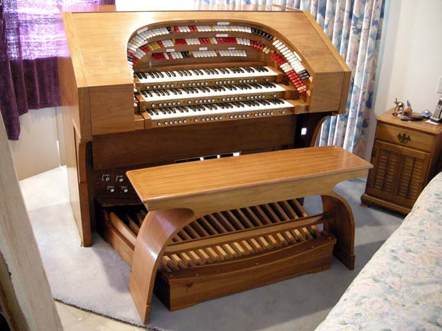
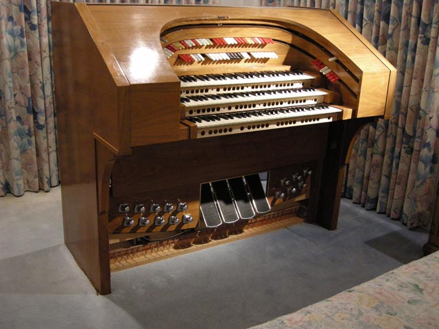
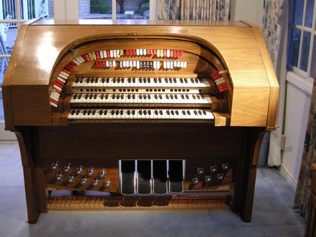
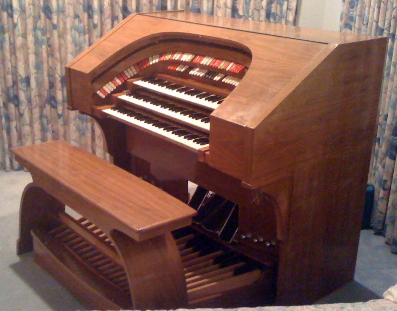
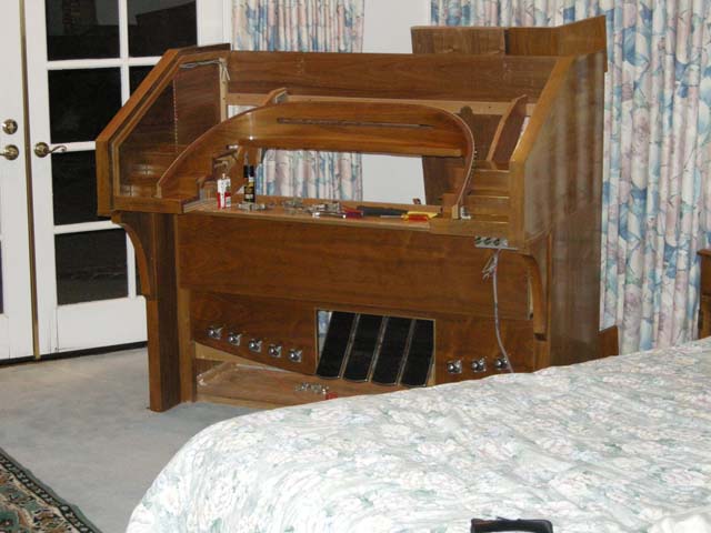
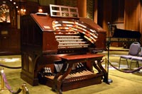
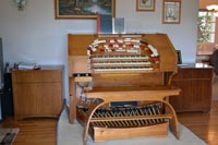
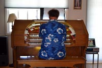
I have been using the software product Hauptwerk together with samples from Neil Jensen's Keymedia Productions Connoisseur Theater Organ and my existing Rodgers 945 concert organ to play my theater organ music since early 2008. You can see how I do this on my Organ Design page. I probably would have been quite happy playing this way forever, using my touch screen display to control stops and my Rodgers combination pistons to make quick changes. However, when my friend Ken Rosen (who has a very nice two-manual Wurlitzer pipe organ in his studio and lives only three blocks from me) announced he was ready to give away a large three manual theater organ console, it was an offer to good to refuse. The console in question comes from an old analog Artisan organ from the 60s, probably their "Oriental" model. These were very large kits that were advertised in such places as "Popular Mechanics". This one would have cost approximately $7,000 in the 60s and was the top of their line. I have not been able to find any photograph or specifications for this organ in its original state. However, recent research has revealed that the console was once owned by Bob Leonard, an organ enthusiast who lives near China Lake, California. The photo below shows the console as customized by Bob, though it was not longer playable at the time the photo was taken in 2007. Bob, if you are reading this, thanks for making the console available!
|
|
You can look at the specifications I have designed for this organ.
The latest recording of the organ is my transcription of George Wright's recording of La Danza. Here is my arrangement of "Get Out, Get Under the Moon." It is inspired by the 60s recordings of George Wright. Here is the first recording made on the completed instrument, "Me and the Man in the Moon." It is my transcription of the Jesse Crawford recording. It shows off a lot of what the organ can do. Here is a recording of the tune "High Hat" made with the organ on June 25, 2011 to celebrate two years of progress |
|
Sunday, December 16, 2012 – The Console is complete!
| I was home for just a single day between trips to the East coast, I had been at meetings at NASA's Kennedy Space Center last week and I will be at Goddard Space Flight Center this coming week. Bruno had sent email to me while I was in Florida telling me that the console top was finished and I could get it on this one day. However, since rain was predicted, I asked Karen to pick up the top from Bruno on Saturday. Hence, when I arrived at home, the top was waiting for me. I took it to the lab and restored the wiring to for the music rack. Bruno had to remove this during his work. When Karen and I placed the top on the console, I had a bad surprise. The bolster was indeed sitting a bit too high and it was forcing the top to ride high at the front of the console so it no longer fit correctly. After about an hour of thinking, I came up with a solution that would avoid any modification to the bolster assembly. I decided to raise the top by 1/4". This is accomplished by inserting a 1/4" thick wooden piece under the console top hinge where it attaches at the rear of the console. I did not have a long enough piece of oak so I called Bruno. He cut a piece of poplar to the required 1/4" by 57 1/8" size. I had told him the depth was not critical as long as it was at least 3/4". I drove to his workshop and picked up the strip. When I got home, I discovered that the depth mattered after all! There was a small lip on the inside of the rear console piece that created a small recess for the hinge - and this meant the wooden strip had to be 1/2" or less in depth. I called Bruno again and he asked me to return and use his table saw to rip the piece to 1/2" After my second trip to Bruno's in a single day, I returned home with the correct size wooden strip. Karen and I placed it and the top on the console and I declared the console complete. |
 |
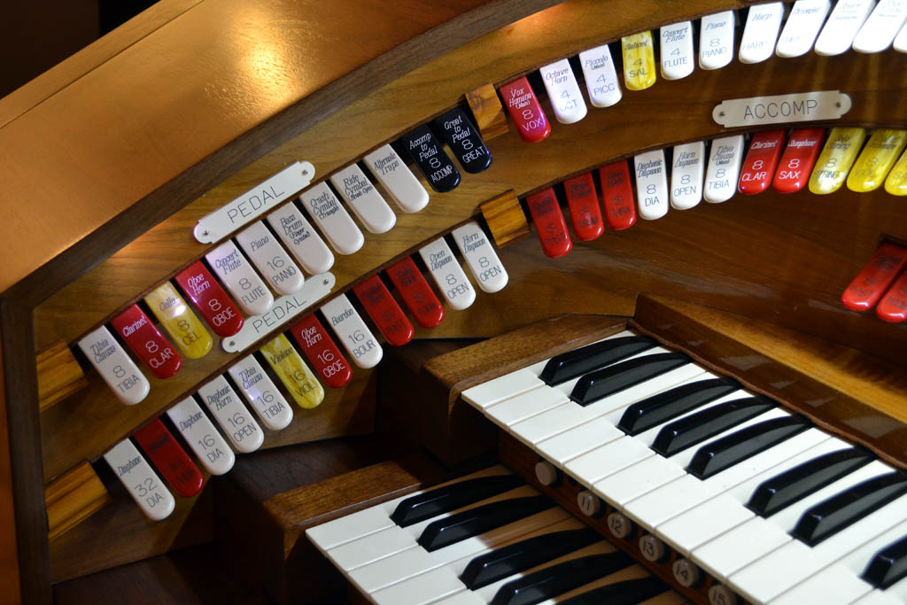
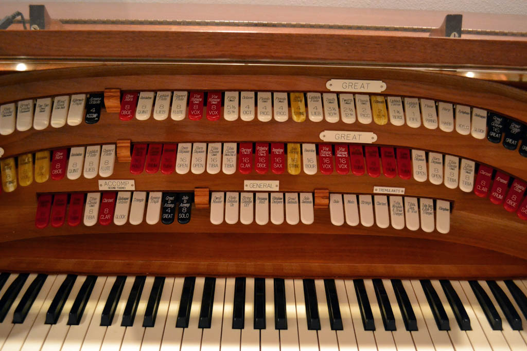
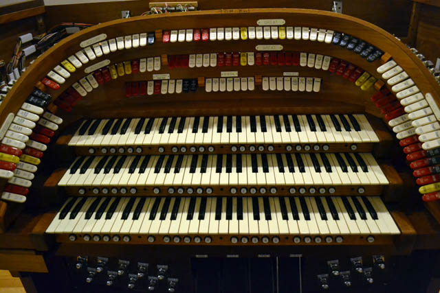
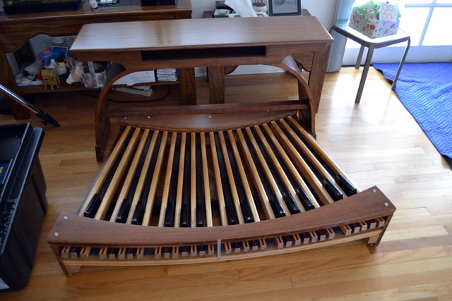
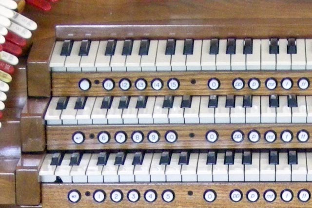
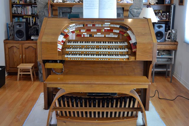
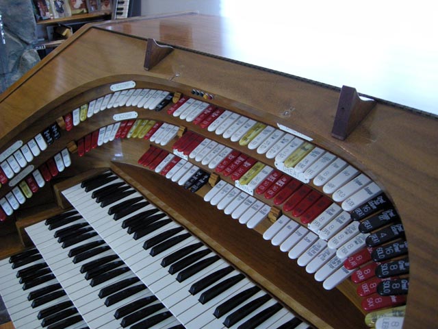
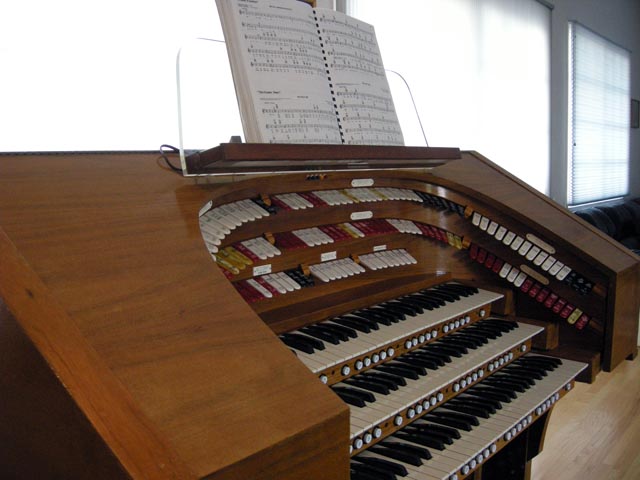
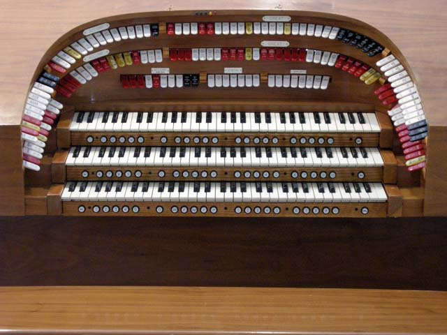
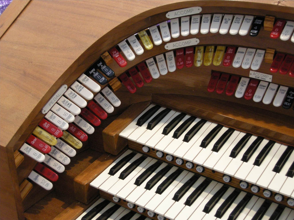
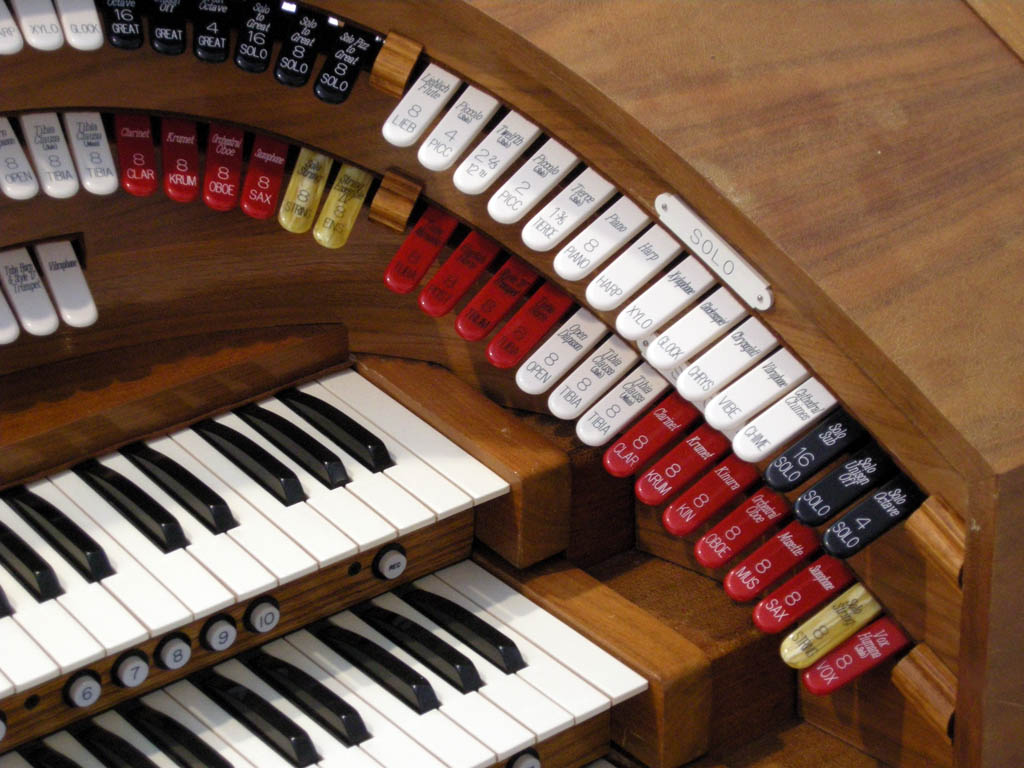
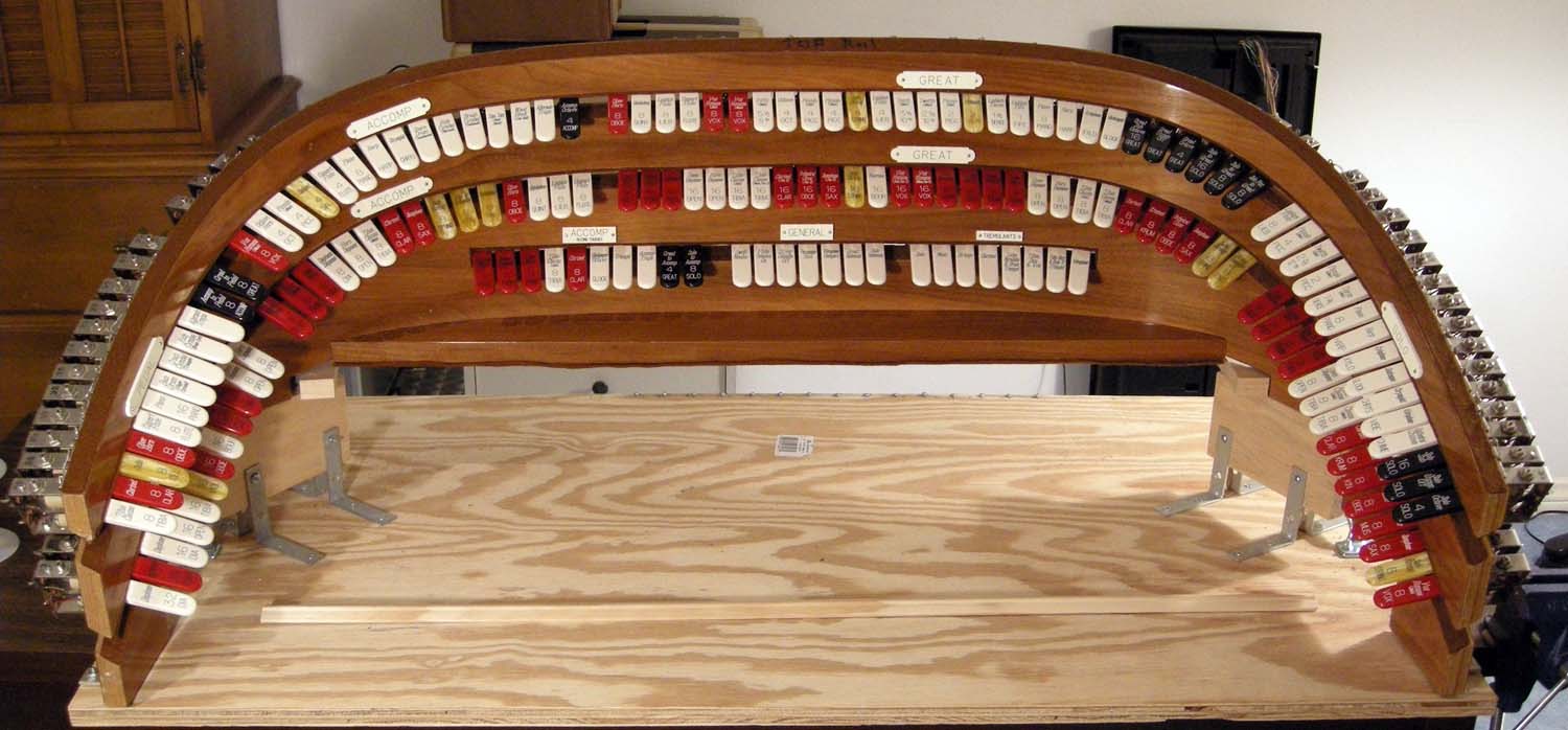
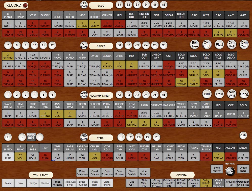
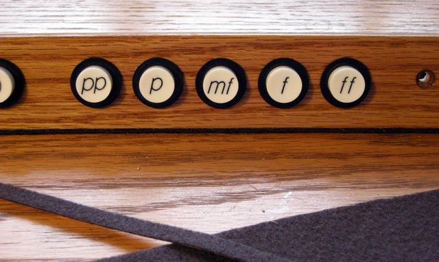
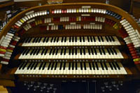
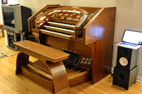
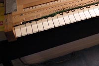
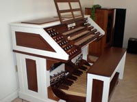
| Now that I have a complete theater organ console - which plays beautifully - I took the mandatory console sweep photographs, Here you can see the pedal division. It is very complete for an organ of this size. The use of the "alternate traps" tab allows for a reasonable variety of traps. The piano stops on the organ use Key Rig rather than Hauptwerk for extra realism. |
 |
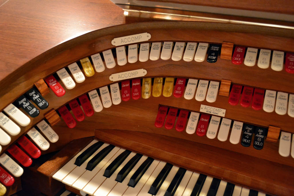
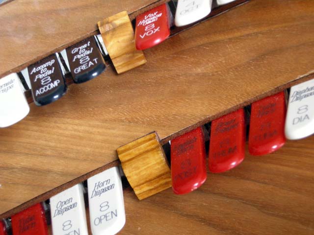
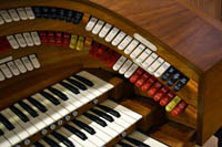
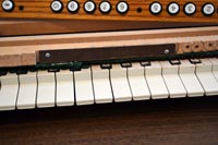
| Here are the accompaniment stops, including the second touch stops on the straight rail (which is actually not straight on this console!) |
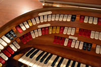 |
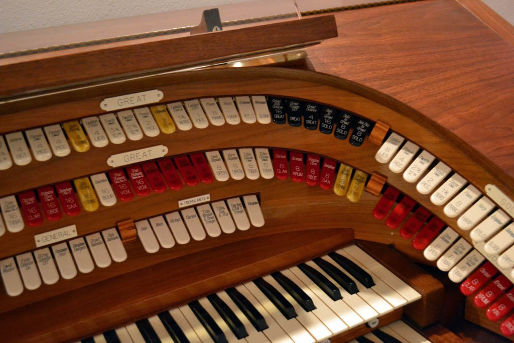
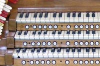
| Here are most of the Great stops - and the entire straight rail. In addition to the second touch stops, the straight rail has the usual compliment of replants as well as a set of "general" tabs to control things like the celestes and sostenuto functions. I relegated all non-traditional functions (including MIDI stops, combination system memories, and transposition) to the drawer so the organist sees only real pipe organ controls on the bolster. The Great is very complete - but some ranks and footages have been omitted because of the limitation on the number of stop tabs. I selected these carefully based on much research and discussions with other theater organists. All omitted ranks are available on the Solo, which couples to the Great. Hence the Great can still be used for a full organ ensemble. It is loud enough by itself anyway. |
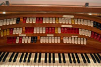 |
| Here are the remainder of the Great stop tabs. Though I omitted a few ranks from the Great, I was not stingy on couplers. |
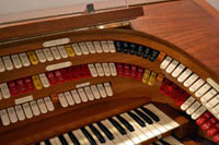 |
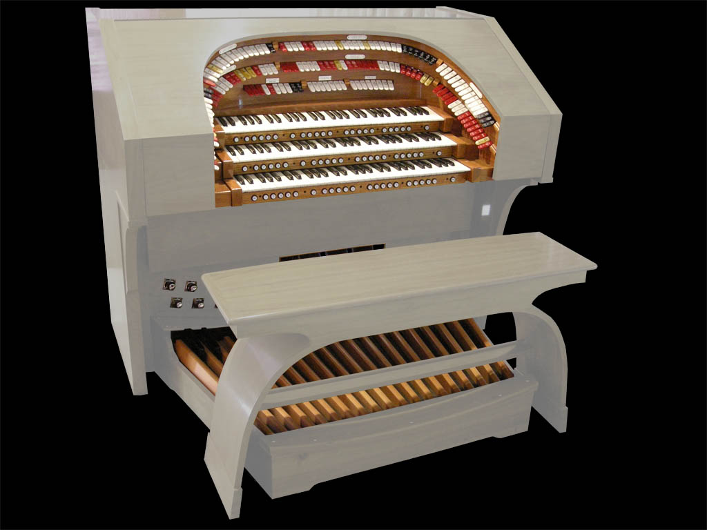
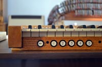
| The solo is also very complete. It has several color ranks that are available only in this division. I included the standard Wurlitzer couplers, but omitted the "Blackpool" couplers as unnecessary for the way I play. I also included many turned percussions.This photo also shows poff the two-tone wood finish on the console. My project is almost complete at this stage. Bruno will likely deliver the speaker cabinets next weekend. After that, I will start the final voicing of the instrument. I will also "wire" in a 12 rank Barton organ sample set that I have acquired. I might buy another large theater organ sample set before the end of the year, while such things are on sale. I'll decide next week. |
 |
|
Monday, December 10, 2012 – The Classic synth module and some clever software
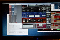
It was time in my test plan to configure the general midi (GM) synthesizer module that resides in my Classic controller. I had remembered to route an audio cable from the interior of the controller box when I put the back on the console. In order to use the same stereo channel for Hauptwerk, Key Rig (see below), and the GM Synth, I used "AU Lab", which comes as part of the Mac operating system. Au Lab allows you to connect many audio programs together and provides a mixer and effects (which I am not using, by the way). I configured AU Lab to accept the line input to eh Mac as one of the inputs to be mixed. I then wired the GM Synth's audio cable to the Mac's line input jack. I turned on the organ and enabled the GM stops - and I heard nothing! In case I did not understand Au Lab, I tried sending a known input to the line in and it worked perfectly. The GM synth was not working. I took the back (actually only one section of it) off the console and opened the controller box. I discovered there was no GM synthesizer there!
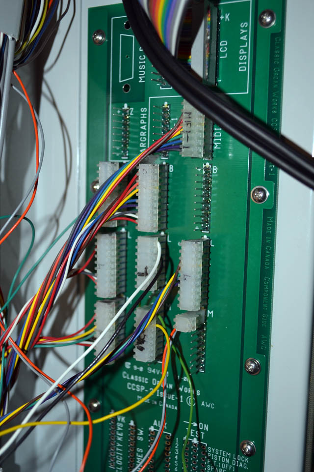
There used to be one - and I had played it before. Then I recalled that I had to replace the mother board in the controller box a while ago and I probably hadn't tried the GM synth since then. I must have shipped the synth back to classic with the old mother board! A quick email to Classic confirmed this and they shipped a new synth board to be the next day. It arrived last today and I plugged it into the mother board - and still I had no signal. However, when I looked through the block diagrams that Classic had shipped me with the controller, I discovered there was a jumper on the mother board that had to be repositioned to route the MIDI signal to the GM board. I moved the jumper and I had synth sounds again!
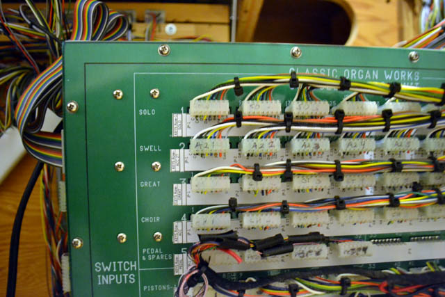
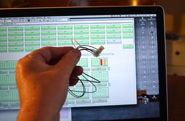
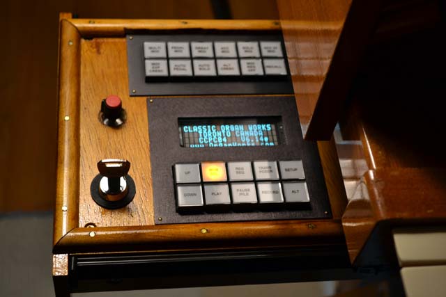
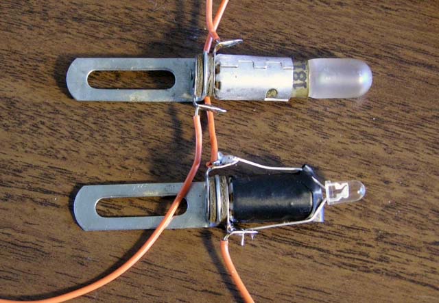
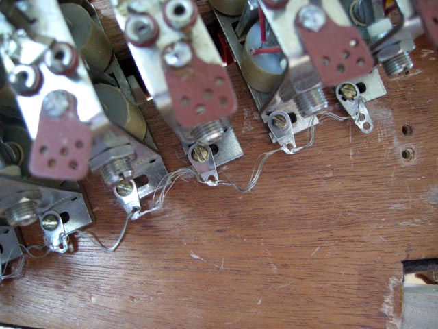
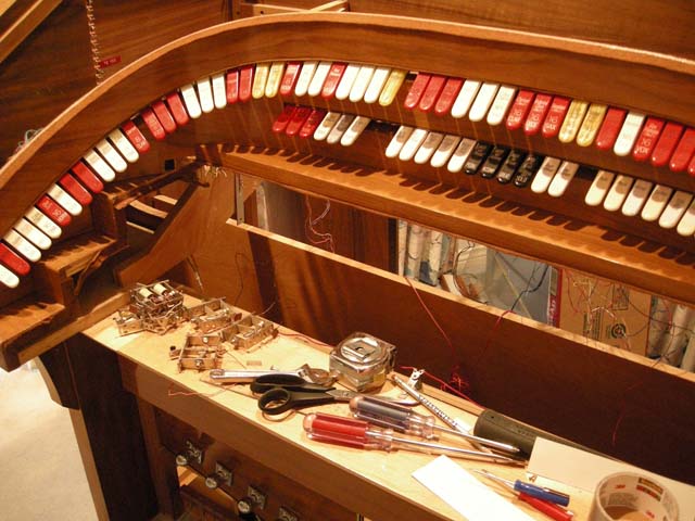
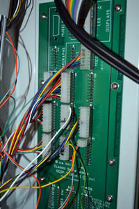
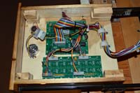
While the console was open, I fixed the only remaining problem I had found through my testing - two reversible pistons on the solo for which the piston light was not working. Both these problems were caused by my having placed connectors improperly on the side of the controller. I had used old photos of the controller to place them this way - and I must have changed their position to make them work! I too this photo of the controller to document the correct positions. |
 |
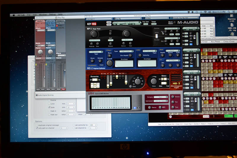
| I have had to do a bit of software work on the Mac to make everything work properly. I wanted to continue using m-Audio's Key Rig to provide the piano rank for the organ. However, Key Rig seemed to stop functioning in Mac OS 10.8 and would not run on my Mini. After corresponding with m-Audio's support people, I was about to buy a new soft synth when I thought I would try a little more hacking. I had already determined that the only thing stopping Key Rig from working was a small application that the user has to run to tell Key Rig the location of its data folder. The application was written in PoiwerPC code which is no longer supported by the Apple runtime environment. I looked at the preference file for Key Rig (its a "plist" file, for you Mac people) and found that it contained a string with this folder location. I edited the file to have the string point to the data folder's location on my Mini. At this point, the latest Key Rig updater file from m-Audio ran after which I could run Key Rig again! I now had my piano rank again. I "wired" it so it keys from Hauptwerk and I also wired the sostenuto switch to act as a piano damper pedal. |
 |
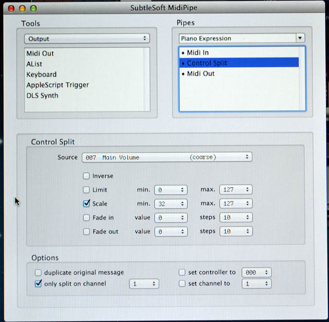
The last sep it getting the supporting software exactly the way I wanted it was to "enclose the piano." This meant wiring it to the percussion chamber expression pedal. This is not so simple. If you wire it according the HW instructions, by using the output defined in the continuous controller menu for that expression pedal, then you get a midi controller signal that goes from 0 to 127. Unfortunately, this means the piano sound goes completely silent when the chamber is closed - which is very unrealistic! Instead, I defined the expression pedal output on a new virtual midi channel and used MidiPipe (shareware for the Mac) to filter the midi data and send a new volume output to Key Rig. Here you can see the critical piece of this, a filter that rescales the 0-127 data to be 32-127 data. I settled on 32 by trial and error. With things set this way, the piano expresses about the same amount as the other tuned percussions.
All is now completed except the console top and speaker cabinets, which Bruno Legarce should deliver very soon. |
 |
|
Wednesday, November 28, 2012 – Tidying up the Console and a new computer for Hauptwerk
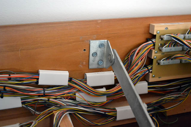
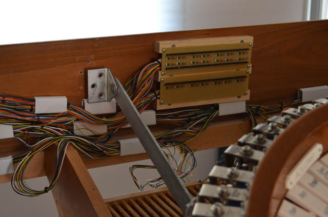
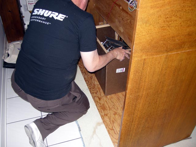
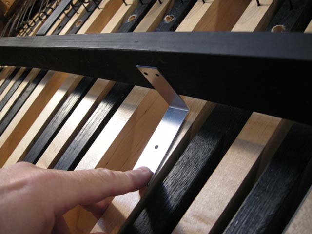
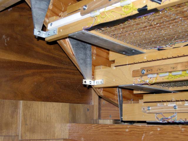
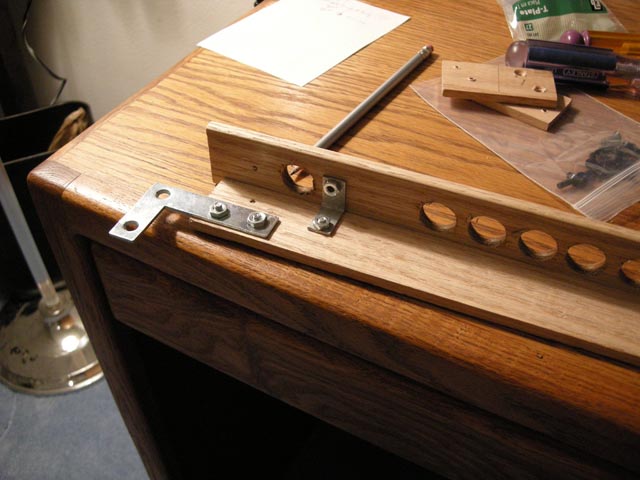
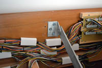
| It is now time to put the finishing touches on the console. For the very first time, I secured the metal brackets that steady the bolster assembly. There secure with large metal plates to the inside rear of the console. They did not match up with any of the existing holes, however! I simply made new ones in the right places. The bolster is now very solid. |
 |
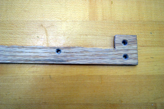
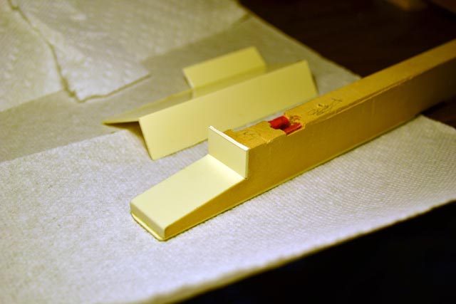
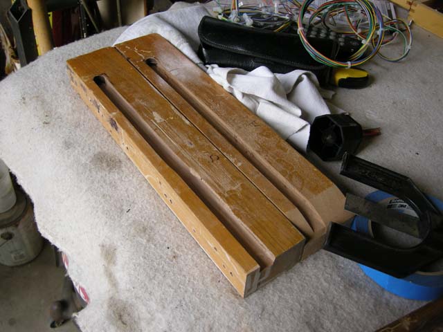
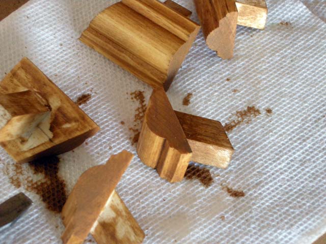
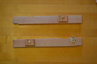
| I had Bruno remove the wooden beam that sat under the accompaniment keyboard when he refinished the console. This was necessary to make room for the second touch contacts. However, this also left the bottom of the accompaniment (including the second touch assembly) open to the air. I was worried that some organist would, in a fit of rage or insanity, bring his or her knee up against the contacts and put them completely out of alignment. Hence I needed a new cover to sit under the accompaniment keyboard. K decided to attach it entirely to the key cheeks so that it could lift out of the console with the keyboard as a single assembly. Here are to lengths of nice lumber I used for the sides. The notches are required to clear the second touch assembly mounting angles. |
 |
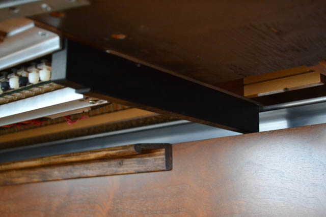
| Here is one of the side pieces attached to the underside of the key cheek. It is now painted black to add a stealth quality. The notch at the front will accommodate a metal angle on the cover assembly. |
 |
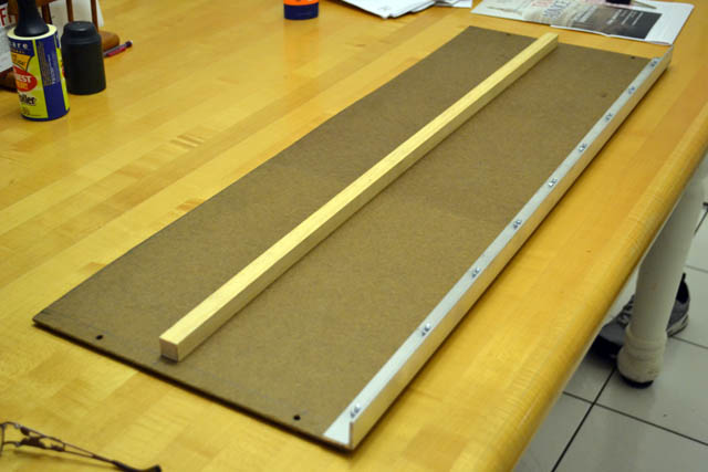
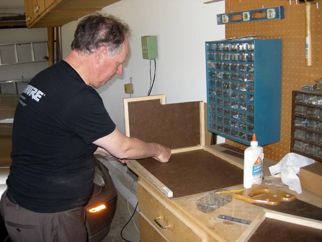
| Here is the cover assembly on my workbench. It is fashioned from Masonite with a length of 1"x1" to provide stiffness. I screwed a length of aluminum angle to the front which will close off the gap under the keyboard. |
 |
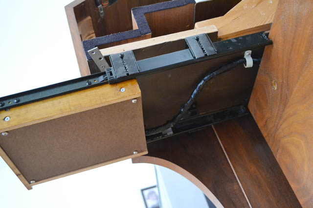
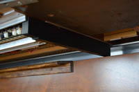
| Here is the cover in place on the organ and painted black. It completely seals off the underside of the accompaniment keyboard, providing excellent protection to the second touch contacts. I think this might be the last assembly I need to fabricate for the organ! |
 |
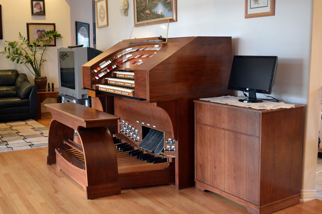
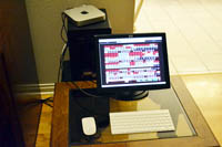
| I purchased an Apple Mac Mini, 2.3 GHz i7 computer to run Hauptwerk (and other software) for the organ. It is dedicated tot he organ and will reside in one of the speaker enclosures when they return from Bruno's shop. Here you see the Mini sitting atop one of the speakers. I am using a small existing monitor to set things up. I also purchased a wireless keyboard and mouse so I can control things from the front of the console if needed. In addition, I installed software on the Mini and Karen's iPad so that I can control the Mini from the iPad. This will make voicing much easier when I get around to that. All that is left is getting the console top and speaker cabinets back from Bruno and everything will be completed. |
 |
|
Friday, November 16, 2012 – Completely working - and with a back!
| After I returned from Washington DC on Tuesday, I spent spare time during the week "wiring" the stop controls to Hauptwerk. By Friday morning, the organ was completely playable - but without combination action. I was home early on Friday because of a doctor's appointment. I spent about an hour testing the SAMs using the Classic control system's internal diagnostics. Everything worked the first time except for a consecutive group of four SAMs in the Solo Division. My master wiring spreadsheet quickly indicated the errant cable - except I misread my spreadsheet and spent 30 minutes chasing down the wrong cable! After I discovered my error, I reseated the bad cable and all 165 SAMs were working. |
 |
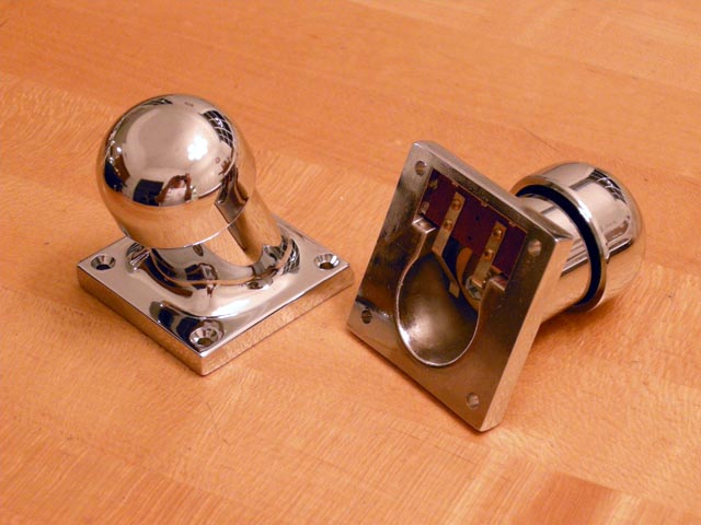
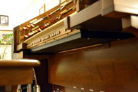
| This far, my Classic Organ Works controller (the "gray box") has been held closed by two little screws. This has allowed me easy access to the interior to set switches and check things out in general. I no longer need this easy access. My last act inside the "box" was to route an audio cable from its onboard General Midi Synthesizer to the outside world. You can see it in this photo as the black cable curving down at the left. Classic included buttons (which I placed in the drawer) to allow GM Midi sounds to be played from any of the five divisions - including the second touch. I then securely closed the box using a set of small screws that I had been saving for this moment. |
 |
| In order to make assembly and removal of the console back easier, I routed call the cables that need to exit the organ to a cable tie that aligns with the "mouse hole" in the center back panel. There are four such cables: The main organ AC power, a switched AC connection to drive the powered monitor speakers, a USB cable that carries the console's MIDI messages to the Hauptwerk computer, and the aforementioned audio from Classic's GM synthesizer. |
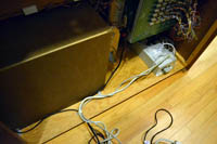 |
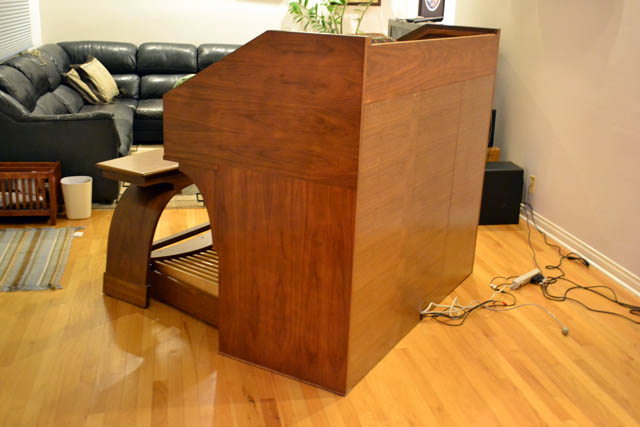
| Her you can see the console with its newly fabricated back. Bruno Legarce fashioned the back in three sections, by my request. This makes each section fairly easy to move by one person. The center section has a small mouse hole at the base to allow the cables egress from the console. |
 |
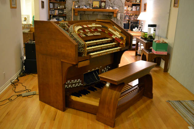
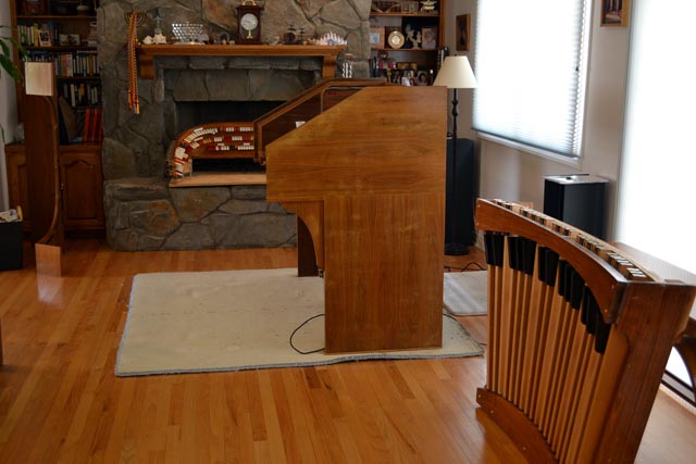
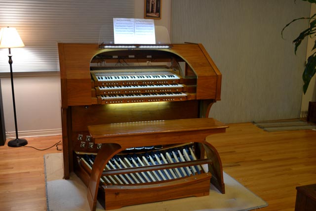
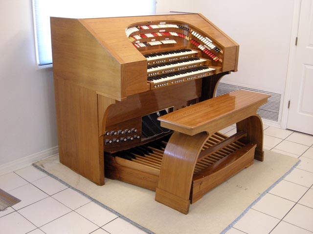
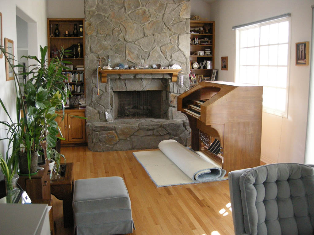
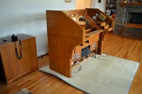
| Here is the organ, completely payable. It is now missing only a few items. Bruno will return the console top soon. I already have the music rack in the lab. Bruno will then return the two Rodgers speaker cabinets which will hide the powered monitors. I still need to buy a dedicated computer to run Hauptwerk. It is a bother to have to hook up my laptop each time I want to play. I am now on the lookout for year-end sales of the Mac Mini. In the meantime, I can now play the theater organ. |
 |
|
Sunday, November 11, 2012 – Coming back together, and playing again
| After a quick trip to Cleveland this week, I returned on Friday and began reassembling the console. Bruno has returned most of the parts so there was a lot to do. I started by reinstalling the accompaniment (bottom) keyboard. I hooked up all the cables and adjusted the primary contacts. I then adjusted the second touch contacts. Surprisingly, it pretty much worked the first time! This is the first time I have ever owned an organ with second touch. IT will take a while before the technique becomes "second" nature. I then continued the assembly process by putting the great (middle) keyboard in place. It did not quite line up with the holes I had made in the console. This worried me until I installed the solo (top) keyboard. The solo lined up with the existing holes. I made a series of measurements and compared things with my Rodgers again. I got the middle keyboard din position and created ne holes to fix it from the sides. I also adjusted the metal triangles that hold it on the back. The keyboards were in place and all working. I also tested the piston wiring. I located several small cable errors - either an 8-pin connector inserted one pin off or a common wire that was not reattached to the controller. By sunday afternoon, the keyboards and pedalboard were all playing properly. |
 |
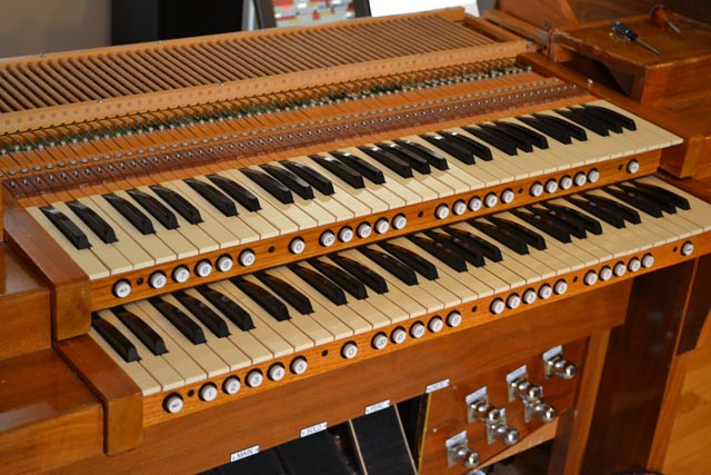
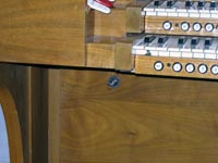
| After dinner on SUnday, Karen helped me reattach the bolster assembly. If I am very lucky, this is the last time we will have to move it. The overall look of the console is excellent. Bruno has done a fantastic job in refinishing the woodwork. He also created small ebony wedges that fit under the two upper keyboards and virtually close the gaps that were visible from the front. I had no time Sunday to actually begin testing the bolster and its 165 SAMs. I had to fly away to Washington DC early Monday. The organ will have to wait until next weekend for more progress. |
 |
|
|
|
Friday, September 28, 2012 – A new switch and a new web page
|
Saturday, September 15, 2012 – Time out for Hollywood
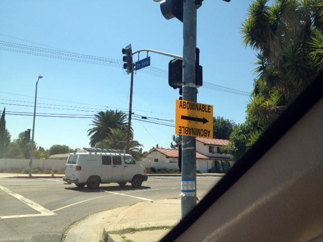
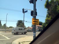
| Over the last couple of days I have reinstalled the power supply, midi interface, and Classic controller in the console. I have also taken the opportunity to straighten out some of the internal wiring. Work had to stop today, however, for a strange reason: our house was being used to shoot an episode of Cartoon Network's Adult Swim series "NTSF:SD:SUV::". If you haven't heard of this show, it may be because it airs late at night. It is the creation of comedian Paul Scheer, who also stars as the leader of a band an antiterrorism squad in San DIego that uses a fleet of SPorts Utility Vehicles. This photo shows a typical yellow film production sign. These are very common in our neighborhood - but they usually do not point directly to our front door. |
 |
| Here is Karen posing for an iPhone shot with the cast of the show. Rebecca Romijn is on the left. Next to her is June Diane Raphael. Karen is next. Brandon Johnson is to the right of Karen. Paul Scheer is on the far Right. Kate Mulgrew, who played Captain Janeway in Star Trek Voyager, is also a regular cast member, but she does not appear in this episode, aside for some voice-over work. THis was too bad because Karen is a huge Star Trek fan. |
 |
| During most of the shoot, the theater organ sat in the kitchen - except for during the one scene that was filmed in the kitchen of course. The crew was very careful with the organ, and all the rest of our possessions. |
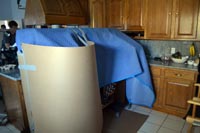 |
| At the end of the day, which was close to midnight, everything was put back the way it started in the morning. Here is the organ, once more in the family room, waiting for me to continue work tomorrow. |
 |
|
|
Saturday, July 21, 2012 – A visit to the console
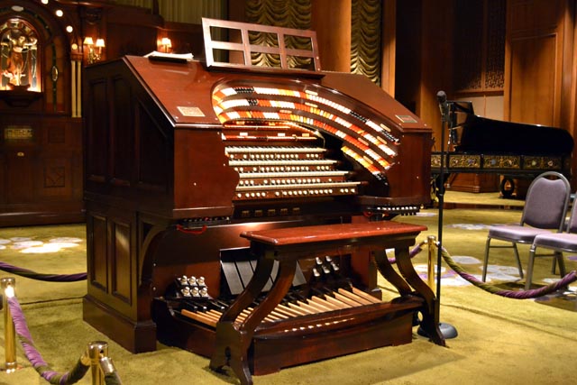
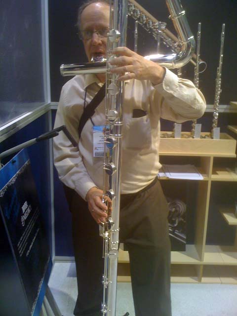
| This is not a photograph of my completed console. I have been up to a lot since I last wrote in this blog. I spent two weeks in Toulouse, France speaking at two technical conferences for my day job. I did get a chance to hear an organ concert of French Romantic music on the famous Cavaille-Coll instrument at St. Sernin's while I was there. I then returned to Los Angeles and immediately took a week off to attend the national convention of the American Theater Organ Society (ATOS) which was being held in Los Angeles. This is the first ATOS convention I had attended in more than a decade. It was strange to spend most of six days hearing never-ending organ concerts. The convention made me want to play my own theater organ - but alas it is not yet complete. The photo is of the 77 rank Wurlitzer organ at the Nethercutt Collection in Sylmar, very close to my home. These people have a lot more SAMs to contend with. |
 |
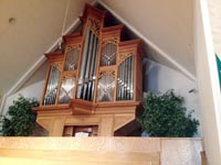
| The following week I played a concert with the Night Blooming Jazzmen at the First Presbyterian Church of Granada Hills. As usual, I tried out the pipe organ. I recognized it from the portfolio that Bruno Legarce had shown me. It is an organ case and console that he built when he was working with Manual Rosales. I played the organ for a while - long enough that the pastor asked if I would be interested in working there! The wood work on the organ is magnificent. I know Bruno was the right person to refinish my console. |
 |
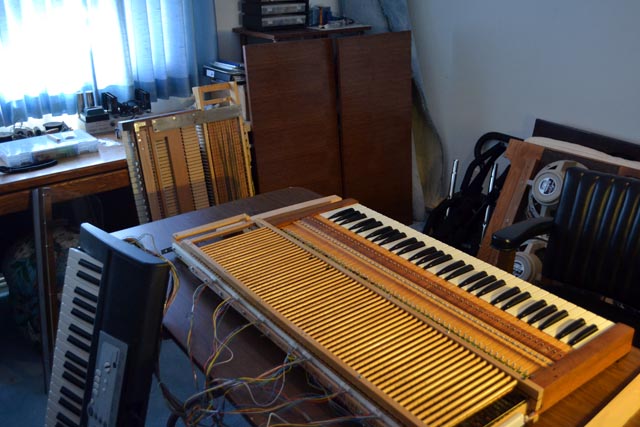
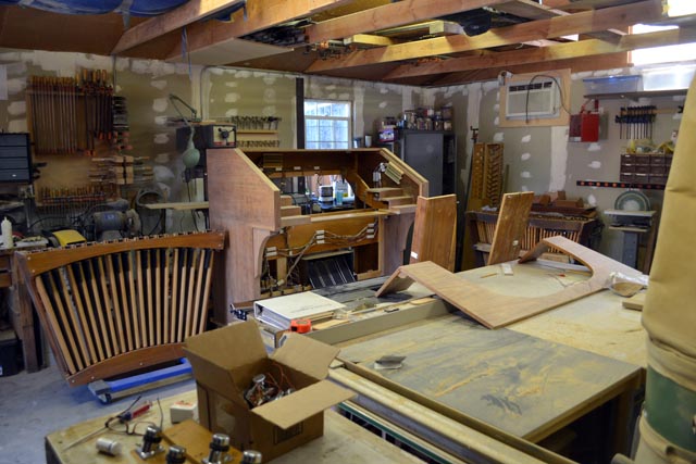
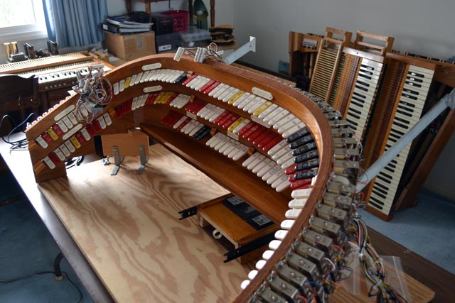
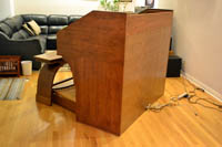
| Today I went to Bruno Legarce's shop, behind his house, to see the progress on the theater organ console. There are pieces of various organs all around the room, as you can see in the photograph. My console is in the center. It is the same shape as when I saw it last, but the wood looks entirely different. Bruno has completed the removal of the old finish and repairing of some of the veneer. The console looks great. You can now tell that Artisan used very nice wood for their consoles. |
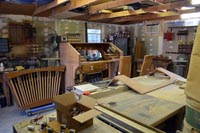 |
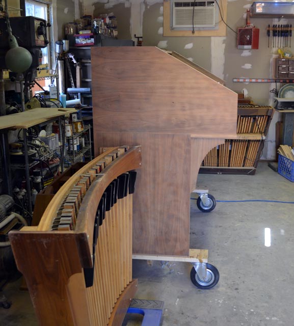
| Here is a closer shot of the console, showing the quality of the wood. I brought the accompaniment manual (complete with second touch) with me to leave with Bruno. We spent a little time seeing how we might modify the crossbeam that runs under this manual to make room for the second touch contacts that now hang below the keyboard. Bruno will do this, fill in some of the wood grain on the console, and finish it, the pedalboard, the bench, the key cheeks, and the speaker cabinets to a dark wood shade. He showed me the various possible stains and I selected a dark one that was close to the darker of the two speaker cabinets. Bruno intends to have the console completed before the end of August - which means I will then begin reassembling the parts and playing the organ again. |
 |
|
Friday, March 31, 2012 – Closing the gap
|
Monday, March 26, 2012 – Final fitting the 2nd touch contacts
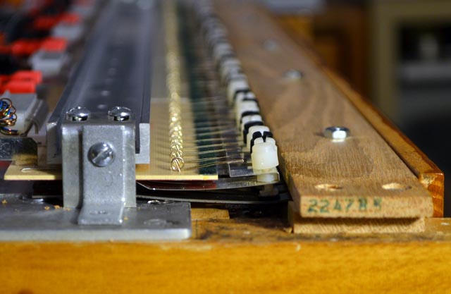
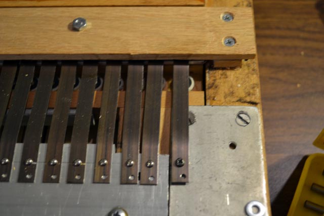
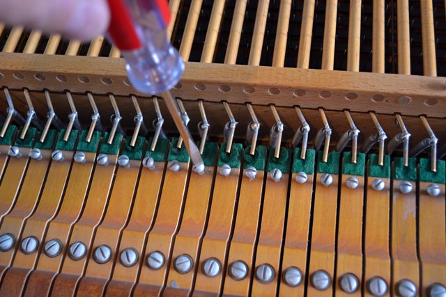
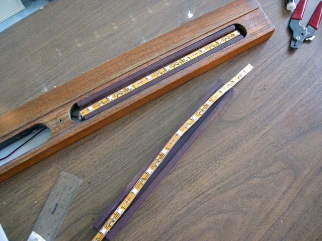
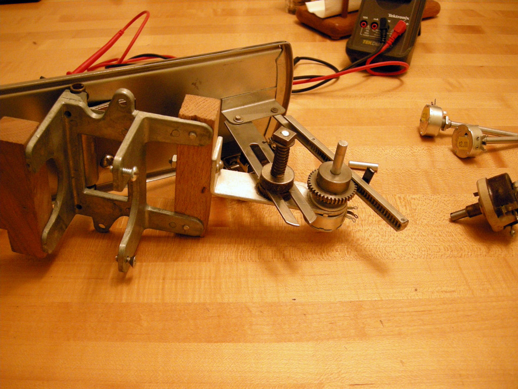
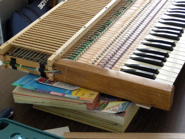
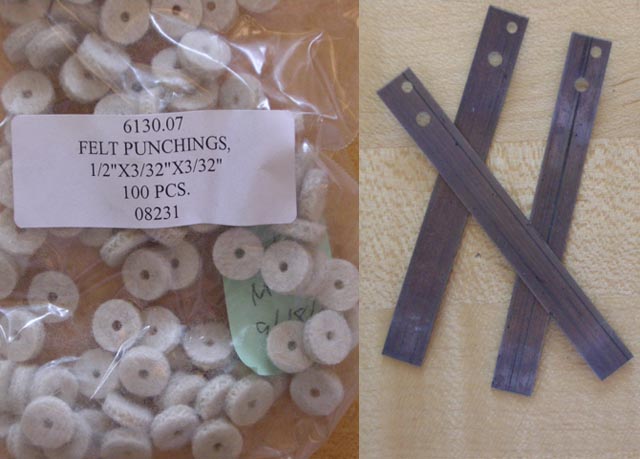
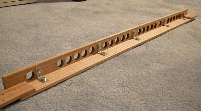
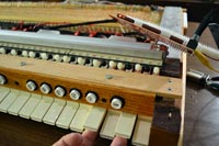
| Now that I knew the Peterson keyboard contacts would work, I needed to do final adjustment and mounting. Some of the 2nd touch springs simply did not come to rest on the rail I installed. This meant the corresponding keys had to have additional throw to engage the second touch. In order for this to feel right, I had to pace additional felt washers on the keys' screws. This was not a satisfying fix. Instead I ordered thicker aluminum and created a deeper rail. You can see this in the photo. This solved the problem with the springs, but now the springs would click against the bottom piece of wood that holds the piston rail in place. I therefore had to cut a piece of this board away. I used a coping saw so the line is far from straight - but it never gets seen anyway! With the deeper rail, I also had to mount the Peterson contacts a bit further from the springs. I did this by using only two nuts rather than three for spacers. I had to hacksaw four screws to the new proper length to accomplish this. |
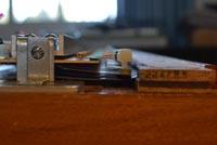 |
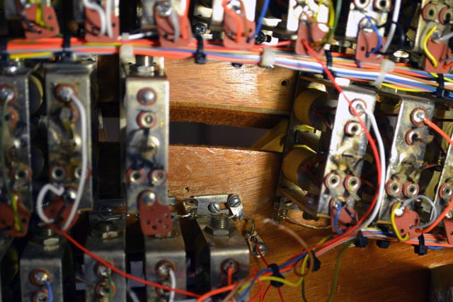
| Here is a view of the bottom of the 2nd touch mechanism. You can see how poorly my cutout is in the board! However, it was quite necessary. |
 |
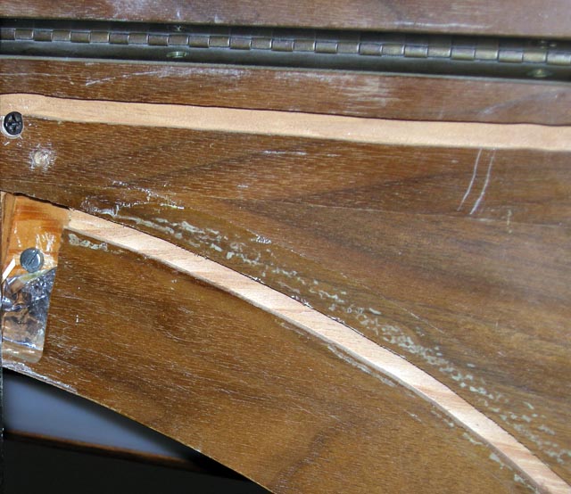
| All the keys now have a reasonable 2nd touch feel. I readjusted all the primary and 2nd touch contact points and everything seems to work correctly. With the keys now having an extra ~1/4" of throw, there is a gap of that same size between the key bottoms and the piston rail. In order to close this gap, At first I thought I would fabricate a new piston rail that is 1/4" taller. On further inspection, I admit this will not work! The keys would simply hit the top of the new piston rail at about the same depth that they would engage the2nd touch springs – completely negating all my hard work. I think I have to live with the gap. The only alternative I can see is to extend the white plastic key fronts down by 1/4", which would be a great deal of work! |
 |
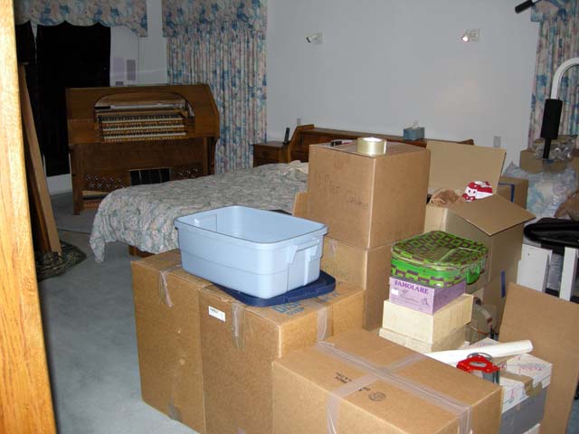
| Bruno came by and picked up most of the rest of the organ. He has finished the major sanding of the console shell. Now he also has the bench, pedalboard, and the two old Rodgers speaker cabinets. Here is the empty space in my family room! |
 |
|
Wednesday, March 7, 2012 – Test fitting the 2nd touch contacts
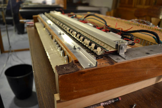
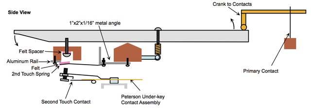
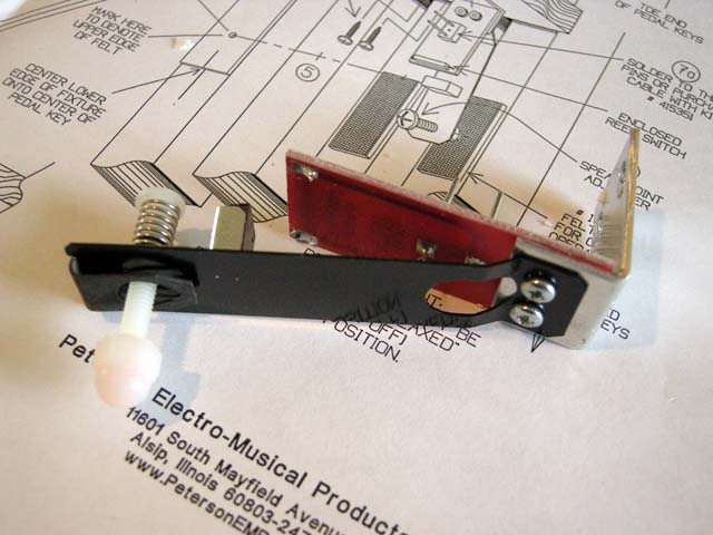
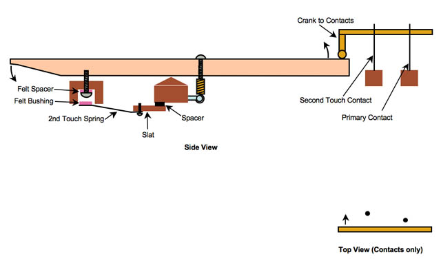
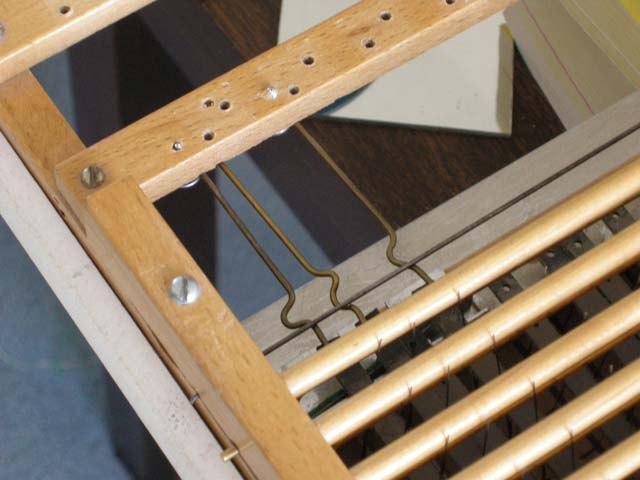
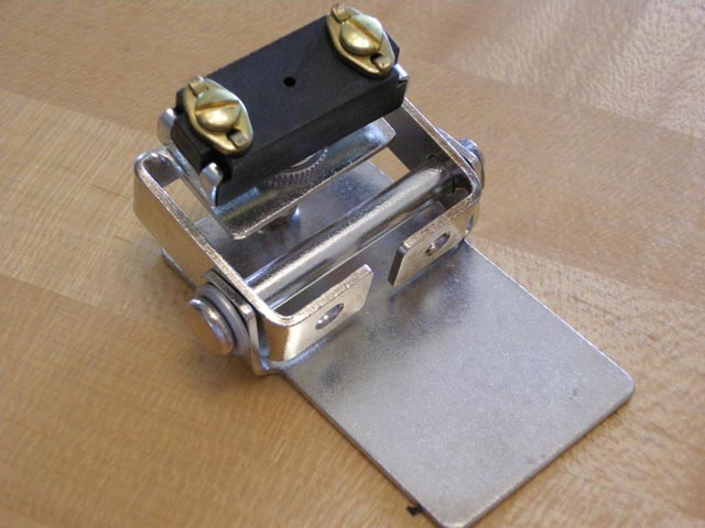
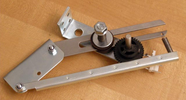
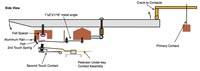
Here is the latest design I have for second touch. The primary contact is simply the existing crank contact on the back of the keyboard. The second touch springs are mounted to the aluminum angle that is in turn secured to the keyboard pivot block. In order to pretension the springs, I have secured an aluminum rail to the forward ridge of the keyboard stop block as shown. I have increased the thickness of the felt spacer that sits on the screw that in turn defines the key throw. I have placed felt on the upper side on the 2nd touch springs so they do not click when struck by the key screws nor when the springs snap back to the rail.
This design assumes use of the Peterson underkey contact assembly, shown at the bottom of the diagram. This assembly is mounted so the 2nd touch springs engage the Peterson contacts. Hence, there is no way to accidentally "fire" a 2nd touch contact. The springs must move before a 2nd touch note can play. |
 |
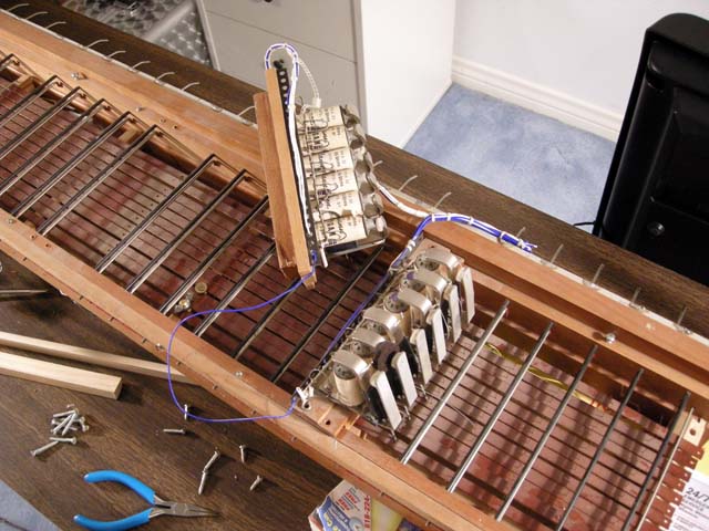
I corresponded with Scott Peterson. Scott has provided much help to me during this project. He graciously offered to send me a set of under-key contacts that I can return within 30 days if I cannot make them work in this configuration. This complicated my testing slightly because I had to come up with novel ways of mounting the contacts that did not damage them in any way! It took two evenings of thinking - with Karen's assistance - before I settled on a method that would hold the contact assembly securely in the right position (or at least close enough for testing) and not modify the Peterson parts in any way. First I had to verify that I could affix some metal brackets to the bottoms of the key cheeks. Since the console is out for refinishing, I had to search my extensive photo library to verify I could do this and still fit the keyboard into the console.
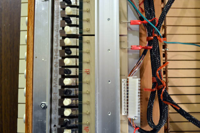
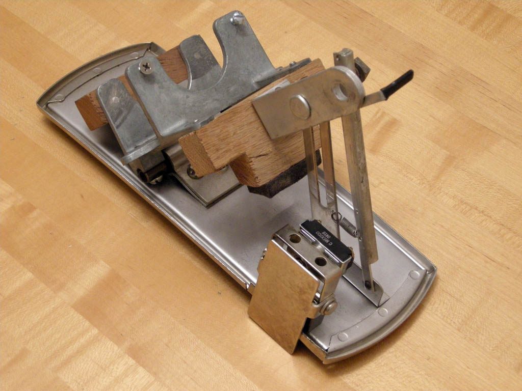
I mounted small metal angles on the two key cheeks. These in turn attach to the two metal angles that came with the Peterson assembly. I turned the Peterson angles upside down and also used a stack of nuts as spacers so that the Peterson metal channel is suspended approximately the right distance below (above in the photo since the keyboard is upside down) the 2nd touch springs.
The small circuit board visible on the right is the Peterson pedal contact circuit card - see below. |
 |
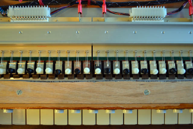
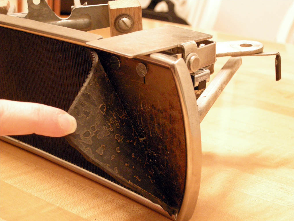
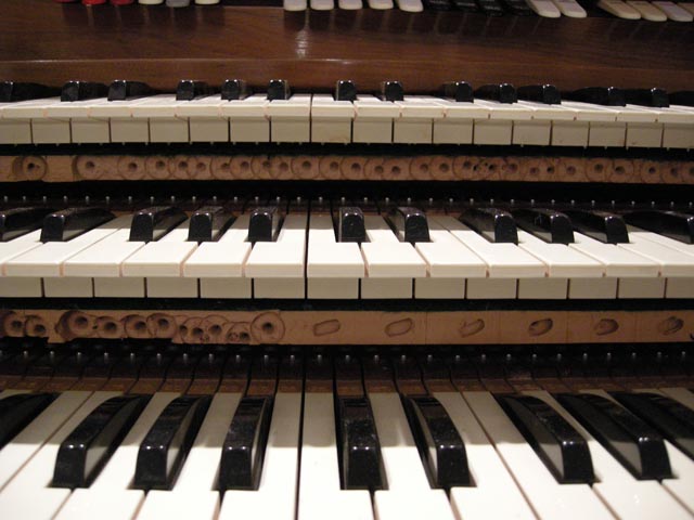
| Here you can see, in end view, how the parts fit together. Compare this to the drawing above. When a key is depressed, it goes through most of its throw before tits screw engages the 2nd touch spring. At this point, the key starts bending the spring, resulting in increased resistance. Slightly later, the Peterson contact engages, turing on the 2nd touch sounds. Notice how all of this adds only about an inch of depth to the keyboard. There should be no conflict with the organist's knees. |
 |
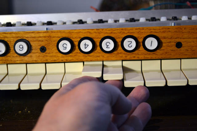
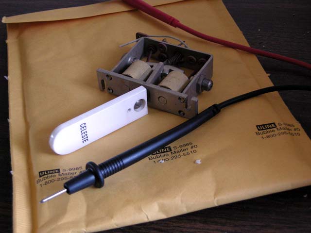
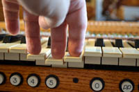
In addition to finding a non-destructive way to mount the contacts, I also had to find a non-destructive way to test them. The Peterson contacts come with a cable that, unfortunately for me, is not compatible with the MasCon connectors I use. Hence I could not simply connect these to my test keyboard. Instead, I went back to the pedalboard and disconnected its Peterson circuit card. This card has two purposes. It serves as a junction for a removable cable linking the pedalboard to the console. It also contains an array of LEDs that are used to test the pedal contacts. There is no reason the same LEDs can't be used to test the keyboard contacts, since they take the same connectors! I can only test a couple octaves of the key contacts at a time - but that is a minor inconvenience. Here you can see me depressing two keys into their 2nd touch region. You can also see the two corresponding LEDs lighting on the circuit board.
I will do a bit more testing before deciding to buy the contacts (I place that probability at 90% today). Then I will need to mount them a bit better and come up with a cover to protect them from knees. |
 |
|
|
Monday, February 25, 2012 – Second Touch Saga – Part One: Springs
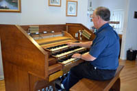
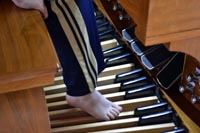
| There is only one big problem left to solve for this project: adding second touch to the accompaniment manual. This one has bothered me for a long time and I have kept pushing it off until later. Now there is no more "later"! Luckily, I had an experience that energized me to work in earnest on the second touch. The Night Blooming Jazzmen was invited to perform at the Fresno Mardi Gras Dixieland Festival in February. Before I left, I made contact with the family that runs the Warnors Center for the Performing Arts in downtown Fresno. They have a completely original 4-14 Robert Morton theater organ that is restored and used as part of the theater's operations. The owners and staff welcomed me and made me feel like a VIP during my short visit. The Robert Morton also has the best adjusted second touch that I have played to date. It inspired me to work harder on my own. Karen took this photo of me playing the organ at the Warnors - though I am way underdressed in my NBJ uniform of the day! |
 |
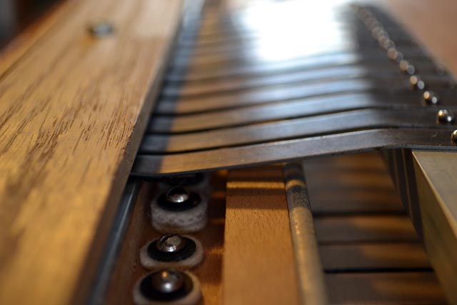
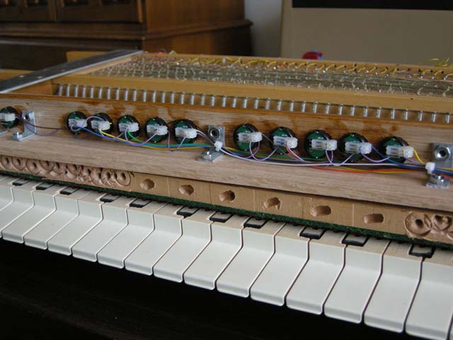
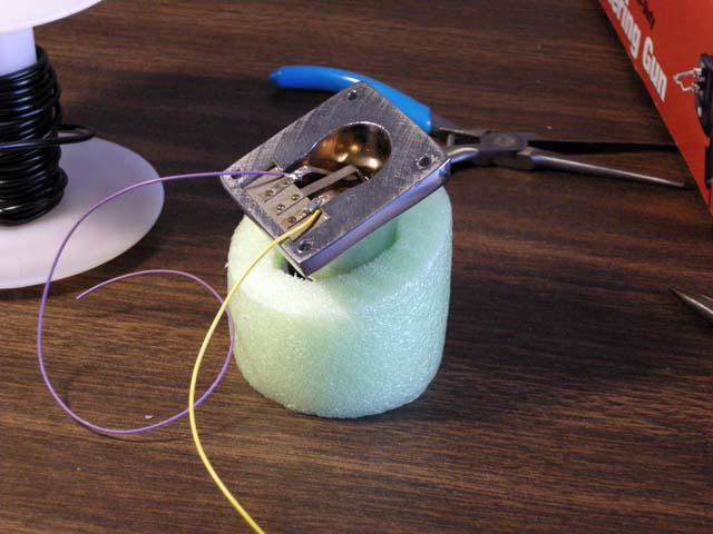
| Although I had experimented a bit using very powerful, yet small, magnets to implement the second touch springs, I soon reverted back to my original concept of using the Wurlitzer replica springs I purchased from OSI, mounting them so they engage the screws that define the throw of the keys. You can see the concept in this photograph. I attached the springs to a length of aluminum angle. This should give enough strength to resist bowing since I attached the angle to the keyboard only at the two ends. I added a piece of aluminum bar stock - visible under the ends of the springs. This forces all the springs to be pre-stressed and provides real definition of the beginning of the second touch throw. Without this piece, many of the spring ends were suspended in midair. |
 |
| Here is a photograph of my first attempt at mounting the springs in this way. The problem with this turned out to be the word "should" in the previous paragraph. I had not calculated the effect of 56 springs pushing in unison. The aluminum angle stock ended up having a non-trivial bow away from the keyboard. This resulted in achieving second touch only in the top and bottom octaves! The concept was sound - but the implementation was inadequate. |
 |
I purchased bigger angle stock. The next largest size required the angle to reach one full inch toward the keys. Karen and I carefully measured this and decided it would work. Here you see the new angle stock, drilled and ready for the springs. The old assembly is shown next to it for comparison. The large angle had two advantages. First, the larger, 1" depth provided increased resistance to bowing. Second, the increased depth (2") allowed me to secure the assembly to the wooden piece that holds the key pivots. This creased a much stronger mounting. |
 |
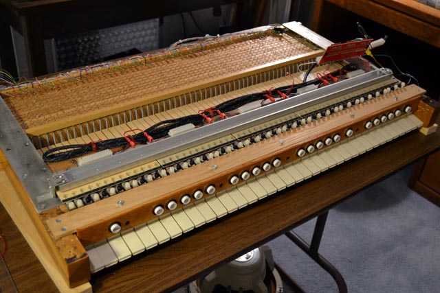
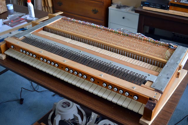
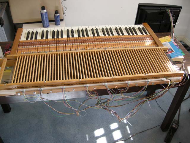
| Here is the nearly finished spring assembly installed. I still need to add the last few springs on each end. They need to be attached a bit differently. It is possible I will completely leave out to high and low "C" because there is no reasonable place to mount their springs. I don't think this will create and real performance limitations. |
 |
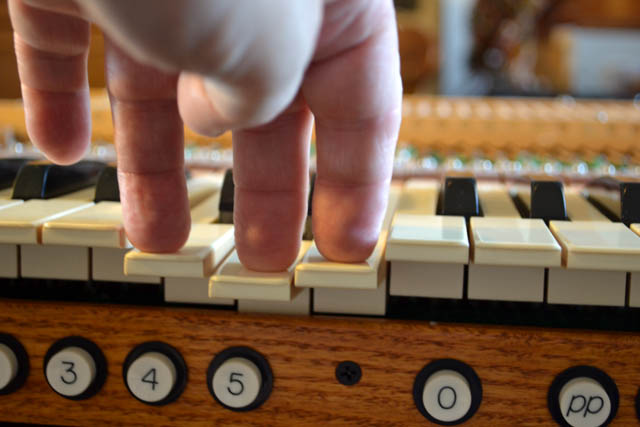
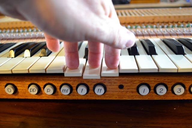
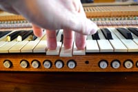
Here is the finished result. I am pressing two keys to the bottom of the primary throw and the middle key to the bottom of the second touch throw. The keyboard is fairly well adjusted. I ended up having to use two thicknesses of felt washers, with deeper ones toward the center of the keyboard.
The next step will be adding the remaining springs and then the contacts. I am now devoting my though toward how I will mount the contacts. |
 |
|
Monday, January 16, 2012 – Some minor keyboard repairs
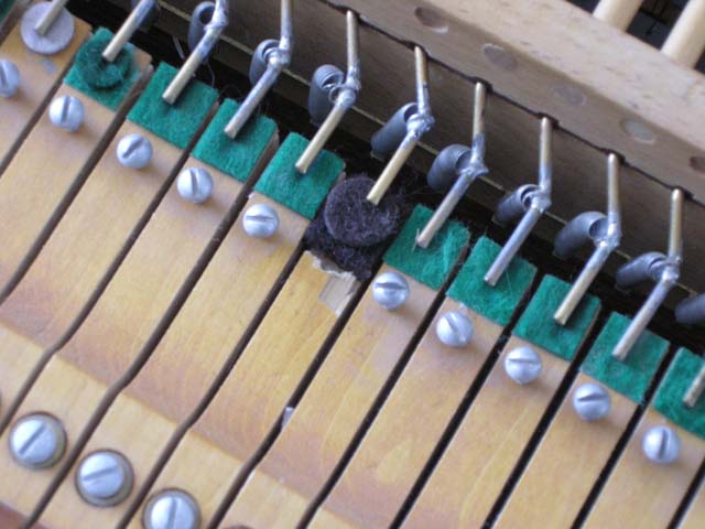
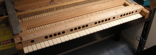
| Now that my family room is once again organ-less, I turned my attention to the three keyboards now being stored in my lab. The upper (solo) manual has suffered from clicks in the top octave. As shown in the photo, the previous owner was a bit too gung-ho in carving wood away from the keybed to make room for pistons. In the bottom half of the top octave, there was not enough wood left to support the felt that cushions the keys at the bottom of their travel. This meant that the keys only stopped when their own wood hit the wood bottom of the keybed, resulting in the aforementioned clicks. |
 |
| I solved this problem by cutting a piece of 1/8" pressboard to fit in the "too-deep" depression of the keybed. I fastened it in place with a coupe of small wood screws, taking care that the piston rail assembly would still fit. The pressboard gives the felt just enough support - even though I did not glue the felt to the pressboard The keys now have the expected cussioned bottoming-out. |
 |
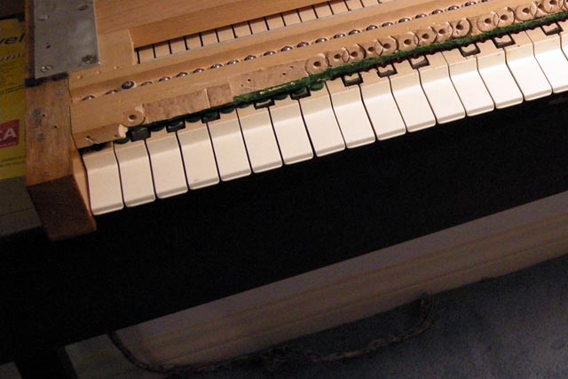
| The second keyboard problem I addressed today was probably also caused by a previous owner's gung-ho drilling to make room for pistons. For some reason the lower couple of keys on the accompaniment manual must not have been safely out of the way. As a result, there were gauges cut into the low C and C# keys as seen in the photograph, which was taken a while ago. Bruno mentioned this when he helped me disassemble the console. He went to his truck and returned with a small piece of plastic about four inches long that was formed into the shape of the bottom of an organ key. It was a real good match for this keyboard too. |
 |
| I carefully removed just the vertical part of the key facing on the two errant keys. I did this by taking a sharp model knife and scoring a line about half way through the plastic just below the bend. I then carefully wedged the blade of my knife between the plastic and wood of at the bottom of the key. I pried the plastic back, away from the key. As expected, it broke cleanly at my scored line .I then used a couple of needle files to carve away the plastic facing all the way to the bend. I cut pieces out of the plastic key stock Bruno had given me and filed them to fit. I then used some glue to secure the replacement facing pieces. Be sure to use glue that adheres to both plastic and wood! |
 |
| The results are excellent. You would have to look very closely to see that new facing is a slightly different color and thickness than the original. |
 |
|
Saturday, January 14, 2012 – Sending the console for refinishing
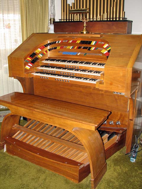
| With only the refinishing, second touch, and installation of a dedicated computer left in the project, I chose to proceed with the one item that is the least work for me: refinishing. I had intended to offer the task to the kind cabinet maker who ripped the piston board molding to size for me near the very beginning of the project. In fact, I tracked him down and sent him some photographs of the console. He rejected the project as being much too delicate and artistic a job for his kitchen cabinet business. I then began asking my local organ industry friends if they had a person they could recommend for this task. The same name kept coming up: Bruno Legarce. I called Bruno and he seemed interested. He came to visit and I showed him the console. It did not scare him off. Bruno brought along a portfolio of organ consoles and pipe organ cases he has built. It was extremely impressive. It turns out that I have played a few of the organs that Bruno has built – so I know he can do a great job. Here is a photo of a recent console that Bruno has built for a customer who is also using Hauptwerk. It makes mine look very sad! Bruno agreed to take on the task when some time freed up in his schedule. That freed up time has now arrived. |
 |
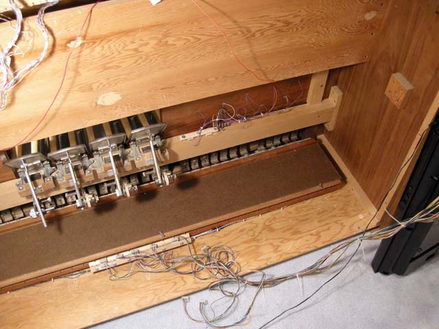
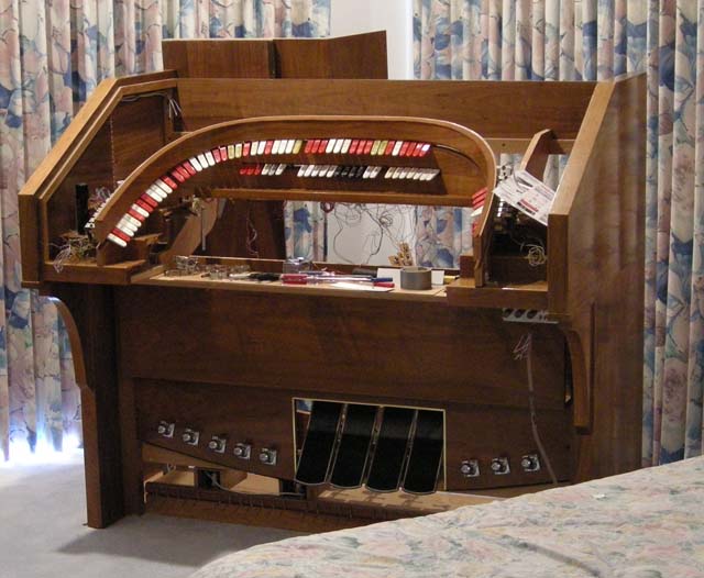
| Bruno came by this morning and he helped me disassemble the console. I thought it was important for him to see how the parts fit together since there are certainly some non-standard solutions here! It was sad to take the organ, which was completely playing (minus the second touch) and tear it down nearly to the state in which I acquired it. Here is a view of the family room with the almost-empty console shell. We removed all the active electronics, including the Classic controller box. |
 |
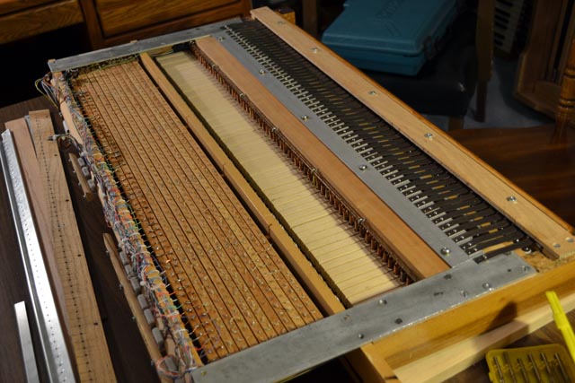
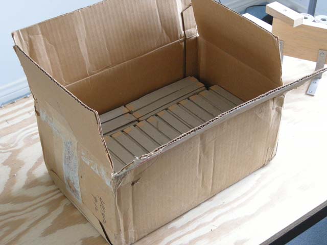
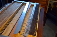
| We moved most of the innards of the console back to my lab. Here is a photo showing them stacked up. You can see the bolster assembly, the three keyboards, and the drawer. The power supply and MIDI interface are just out of view here. The pedalboard is behind two of the keyboards. Bruno will start with the console shell and top, and come back later for the pedalboard and bench. |
 |
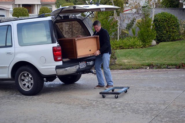
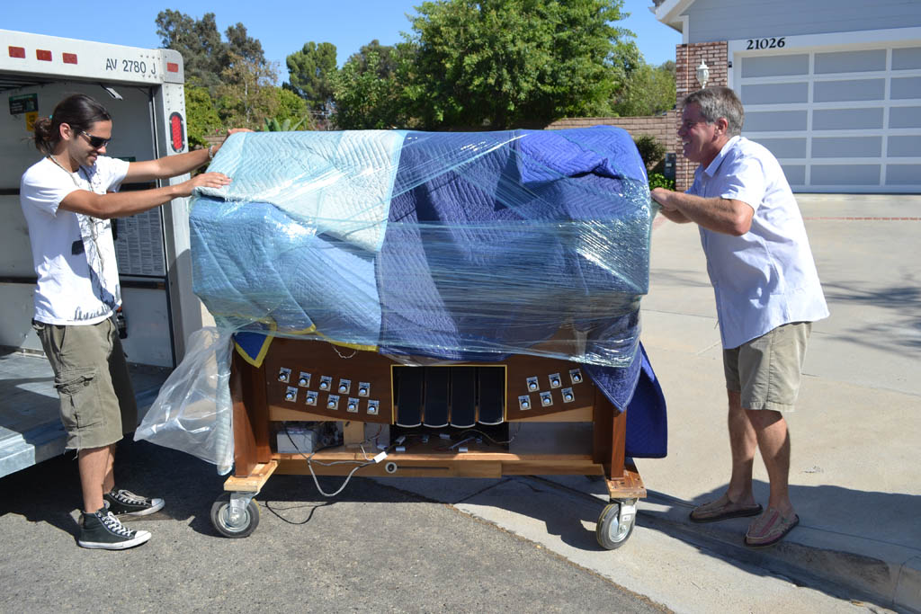
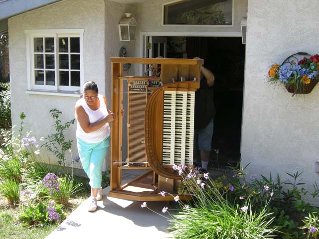
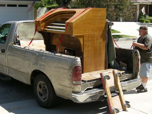
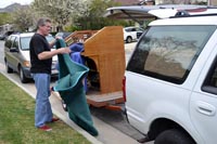
| Here, in a scene reminiscent of the arrival of the console shell, is the same shell leaving my home once more. You can see Bruno securing the shell to his trailer. I know the next time I see it, the console shell will look quite a lot better. |
 |
|
Saturday, November 19, 2011 – Speaker cabinets reclaimed
Karen and I are now working to secure someone to do the console refinishing and minor woodwork. I will report more on this in later posts. In the meantime, I decided to work a little on the speaker cabinets. I have two 1960s Rodgers speaker cabinets left over from my old Rodgers 32B organ. We sold two with the organ and kept two. One of these has been used in my house for the last 15 years as a display table in my living room. The other has served a similar purpose at my parents' house. I went to visit ,my Mother on Friday to celebrate my daughter passing the California Bar. After we returned from dinner. I emptied her speaker cabinet of its amplifiers and speaker cones. The later were affixed to a rear panel. I loaded these separately into my station wagon - so as not to have to carry a single unit that we too heavy. It was already heavy enough for Karen and I without the speakers and amplifier.
This morning, before Karen awoke, I did the same to our Rodgers cabinet. I carried it into the Family room. Karen was right about the finishes being quite different. I am not sure if they were always that way or if ours faded more because it was in a more sunlit room.
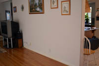
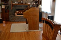
After Karen woke, she helped me rearrange the family room as you can see in this photo. Our fireplace is once again useable. |
 |
Here you can clearly see that the right hand speaker cabinet is darker. I will have the console and lighter speaker cabinet refinished to match the darker one.
The console is still sitting on carpet because it still needs glides added to sit directly on the wooden floor. The console and speakers will sit closer together after refinishing. The console will also sit about 8" closer to the wall.
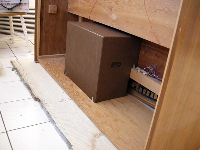
Since the back panels of both cabinets are removed, I simply placed the JPL powered monitor speakers inside, facing the wall. The right hand cabinet contains the subwoofer in addition to right monitor. Although there is plenty of room inside for the computer as well, I am placing it atop the cabinet for now so I can get to it more easily. When I have a dedicated computer, it will live inside. |
 |
|
Friday, October 21, 2011 – Thank you, thank you, SAM I am!
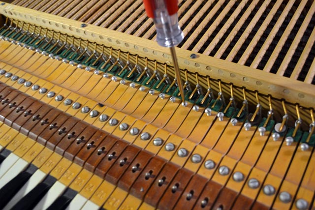
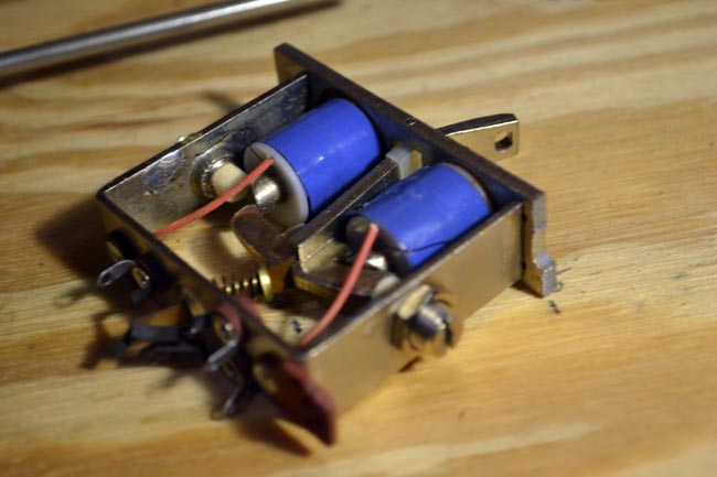
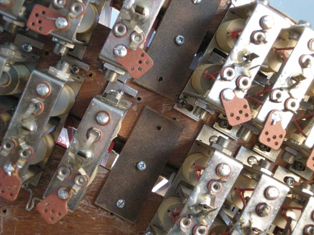
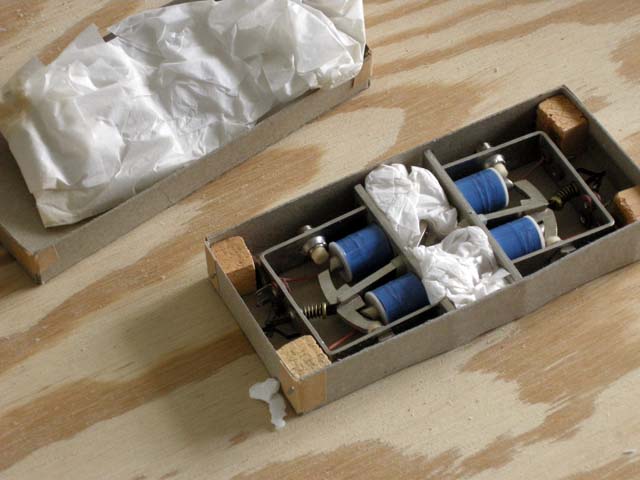
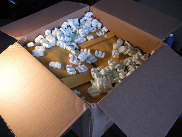
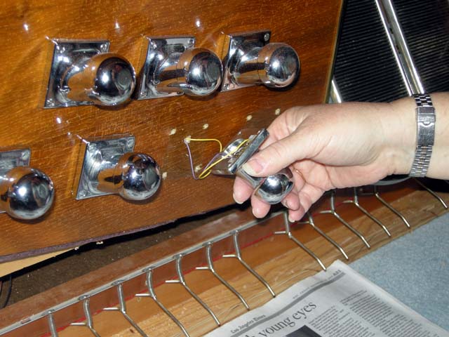
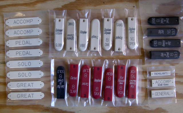
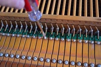
| Last week Karen and I took the bolster out of the organ, placed it in its cradle, and moved it back to my lab. I removed all the errant SAMs. For good measure, I also removed the remaining four tong transplant SAMs as well. Here you can see a gap where I have removed a pair of SAMs. I unsoldered the three wired from each and then carefully unscrewed and removed each SAM. I moved the stop tabs to SAMs from my old purchase of still-in-their-original-box SAMs. I then mounted these. In some cases I needed to drill new pilot holes for the mounting screws since the newer SAMs have holes rather than slots for the screws. |
 |
I had to use a hack saw to cut away metal from the bottoms of three of the new SAMs in order to make them fit. This was not as scary to do now that I know that this didn't hurt the SAMs the first time I did this. Still, it was a bit unsettling to mutilate these essentially brand new SAMs. With nine SAMs replaced, we moved the bolster back to the console. All but one SAM worked! The Solo octave coupler SAM would cancel but not turn on with its magnet. I verified that the magnets both worked and that the wiring was all correct. It had to be a mechanical problem. I noticed that if I held the tab 1/8 of the way down and pressed a piston, it would turn on the rest of the way. I decided that the stop tab angle must have been adjusted too far out of spec - which surprised me since I assumed the SAM would work for any amount of angular adjustment that was physically possible. This was not so - and I consider this a design flaw in the SAM. Karen helped me lift the bolster to a table in front of the console this afternoon. I remounted the last errant SAM about 1/16" higher on the bolster. We placed the bolster back in the console and now ALL THE SAMS WORK. All 165 SAMs are now working.
Now there are only three tasks remaining on the organ console project:
1) Refinish the console,
2) Install second touch on the accompaniment manual, and
3) Procure a dedicated computer for the console.
Task 3 is trivial and should be left until last so as to get the most computer for the same money. I will likely proceed with task 1), refinishing the console. However, first I intend to play the organ for a while! |
 |
|
Sunday, October 9, 2011 – New audio system - It sounds great!
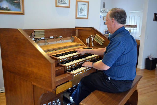
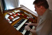
| This photo is a bit of a cheat. It was actually taken on September 24, 2011 - before the previous post. It shows Ken Rosen, my friend who gave me the free console that began this project, trying the organ out for himself. |
 |
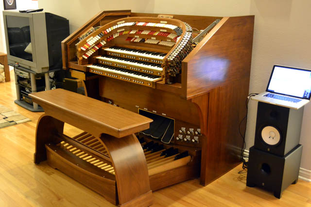
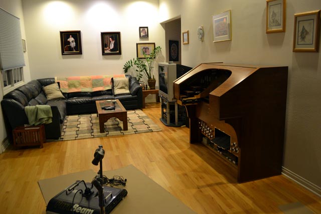
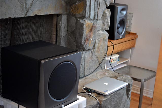
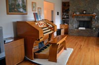
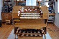
| I spent most of the first week of October in Washington DC. Karen and my wedding anniversary was on October 5 and we were 2,500 miles apart. However, she got me a present anyway. When I returned on the evening of the 6th, I found that Karen had picked up the JBL sound system we had ordered for the organ. It arrived at Sam Ash while I was gone. We unpacked the speakers before I went to sleep. I took the 7th off to prepare for Rosh Hashana services, so I hooked up the speakers before Karen woke. I then turned everything on and played "Oh What a Beautiful Morning" at near full organ. It was a larger and fuller sound than with the temporary vintage HiFi system I had been using up to this point. Karen, however, slept right through all of this! This photo shows the organ with the new JBL system installed. You can see the two powered 8" studio monitors on the cabinets to either side of the console. |
 |
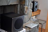
| The JBL system also contains a powered subwoofer. It is shown in this photo taken behind the console. WIth this system, I finally have a well-balanced pedal division and I can actually hear the big 32' diaphone. In fact, several notes in the lower octaves caused rattling in various objects in the room. I tracked most of them down and mediated the problems. However, two notes still rattle the flue in the fireplace! Since the organ will eventually move to the opposite end of the 30' room, I won't worry about these for now at least. Karen and I are going to the Sun Valley Jamboree - a big jazz festival in Idaho - net week, so I will put of reworking the errant SAMs until after I return. In the meantime, I have gotten a lot of time to actually play the organ. |
 |
|
Sunday, October 2, 2011 – Work in progress: Speakers and SAMs
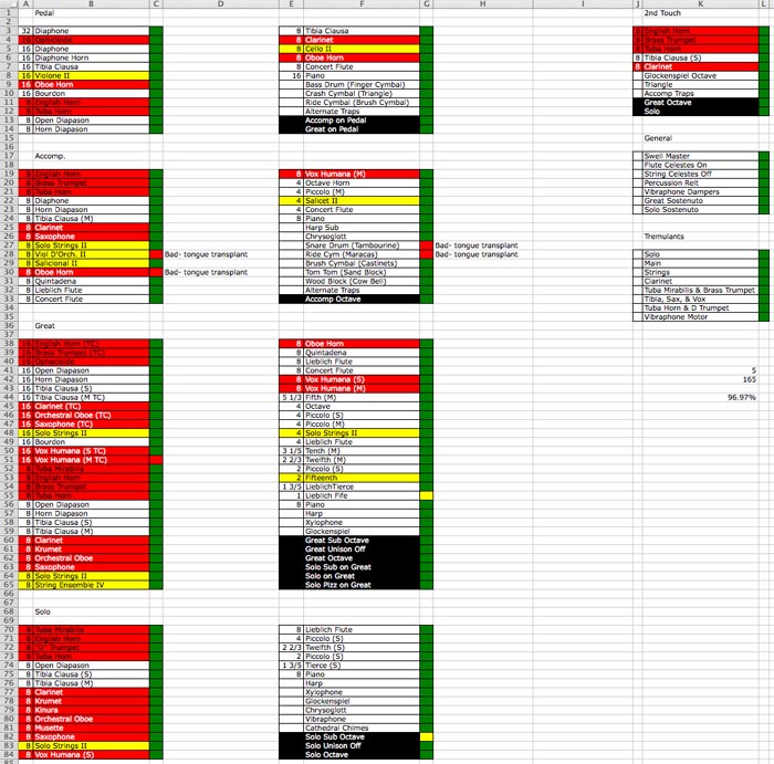
Now that the organ actually plays, it is harder for me to take it apart to do any new work! Karen and I spent some time over the last few days shopping for the audio system. We visited several local music stores and finally placed an order for a pair of JBL LSR2328P powered studio monitors and a matching LSR2310SP powered sub woofer. These will be available to pick up in a couple weeks. I also built up the courage to remove the console top and continue fixing wiring problems with the SAMs. I used four memory levels on the capture system to map each stop tab to a piston so could make repeated SAM tests in arbitrary order. I determined that there were still 11 SAMs that were not working properly. However, four of these looked like easy wiring repair projects. Two pedal SAMs were "wired together" so that a piston set for one would turn both on. The cause was a short between the signal wires on the two SAMs - located on the left circuit board I had built for the bolster interconnections. I used a small file to clear the soldered short and the tabs were once again independent. A second pair of tabs in the Great were linked so that canceling the first one caused the second to turn on. This was due to a similar short - but this time in the magnet wires between the adjacent SAMs. Once more, a few strokes of the file solved the problem.
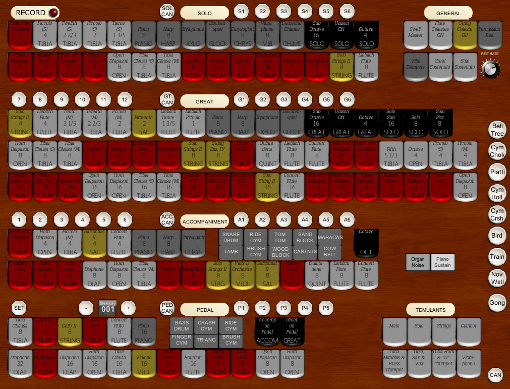
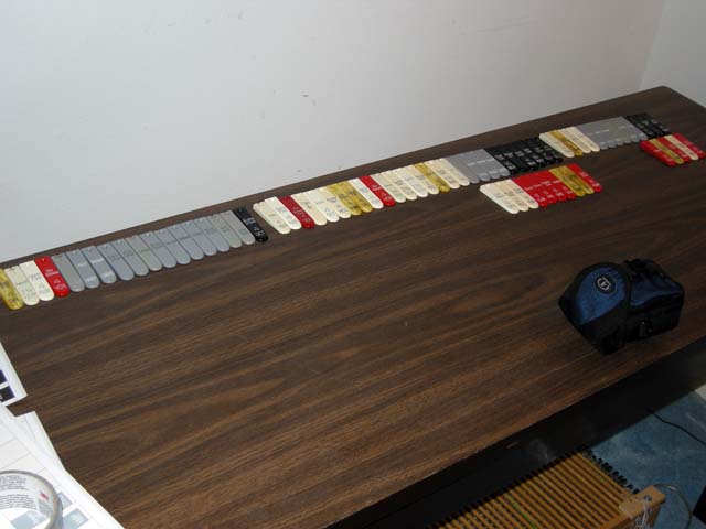
The SAM scorecard shown here lists the current status of all the SAMs on the console. Every SAM is "green" except for seven. Of these, only four are really "dead". The remaining three are "sticky". I have more than enough spare SAMs to replace all of these - so that is an upcoming project. |
 |
|
Monday, September 19, 2011 – Its really an organ now!
Last Wednesday, after an evening spent at my mother's house setting up her new high speed Internet, I returned home to find the new controller board from Classic on ,my doorstep. I carefully swapped out the board and began testing the organ once again. It took a couple evenings to connect everything up once again, carefully checking the functionality after each step. It was all working - modulo the few errant SAMs that I already had identified. By Saturday, I had a fully functional organ for the first time. Every stop and every control works. I programmed everything to Hauptwerk and even spent a little extra time rerouting the MIDI for the piano rank to an external software synthesizer. I now have the following items left to complete the project:
• Replace or repair the remaining errant SAMs
• Add the accompaniment second touch
• Refinish the console
• Procure a dedicated computer for running Hauptwerk
• Add a better audio system
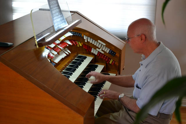
I decided to progress first to the audio system. I invited Cory Edelman, an old friend who is also a theater organist and an audiophile, to visit. He played the organ for a while, as shown in the photo, and gave me some advise on audio components.
|
 |
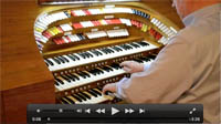
It is time for a new video clip of the organ in action. Still photos cannot convey the fact that the stops actually move and the notes actually play. Hence, I mounted my Nikon 3100 camera on a tripod and played a short piece, "Indiana Lullaby." The idea is to show off the functions of the organ .Click on this photo to run the video. It is in MOV format.
In the video clip you can clearly see the combination action working. I even use the sostenuto effect at the end. I am off to Washington yet again tomorrow so I will not be able to work on this again until next week. |
|
|
Monday, August 29, 2011 – A break in the project to remember my father
On Wednesday, August 24, my father, Ralph Deutsch, passed away at the age of 91. He is the one responsible for my interest in the organ and the one who made sure that I had top notch organ teachers from the very beginning despite the fact that I had not previously studied piano. In addition to all the things he meant to me, my mother, and my sister, he was a successful mathematician, physicist, and inventor. He authored six technical books and held 147 U.S. Patents - so many that he became a patent agent in order to file them himself. He was the inventor of the first digital organ system that became the basis for the Allen Computer Organ that revolutionized the electronic organ industry in the late 1960s.
In order to make room in our home for the throngs of mourners who visited for food and religious services after the funeral last Friday, my daughter and I moved the theater organ to yet another new position.
I will be creating a web page to honor my father in the near future. In the meantime, we have suspended work on the theater organ until at least next week.
Update - Friday, September 9: I have posted most of the web tribute to my father. Click here or follow the new link in the banner on this site. |
 |
|
Monday, August 23, 2011 – A drawer to hold the controls
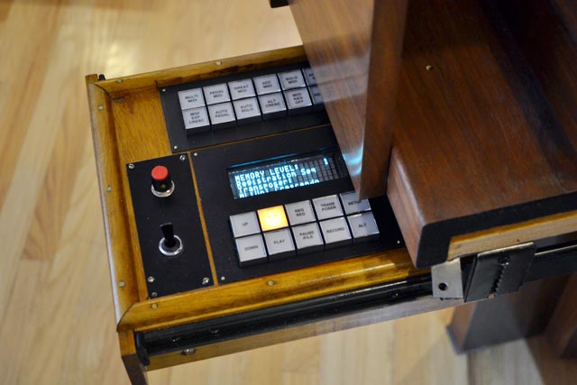
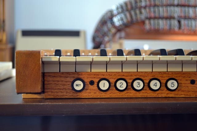
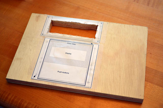
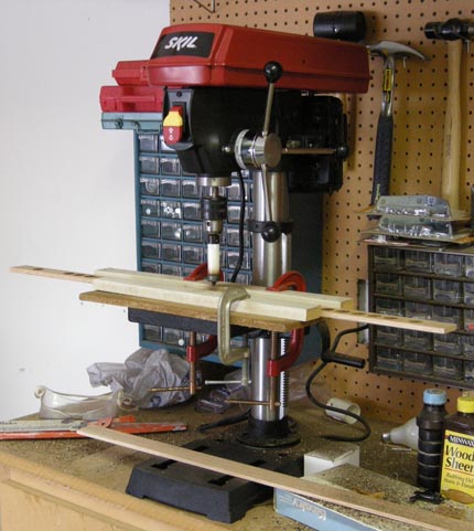
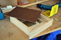
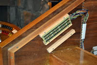
| I began experiencing a strange problem with the console controller system. After working flawlessly since it arrived, it suddenly began generating internal reset signals. At first, this happened every few minutes, but the frequency has increased to the point where a repair is necessary. Classic has been working with me on this and will be sending me some new parts momentarily. In the meantime, I decided to catch up on a few tasks that I had been putting of. The first of these was constructing a drawer to hold the display and button arrays that are used to send commands to the controller. These are, of course, not traditional theater organ controls, so I did not want them to be mounted in prominent positions on the console. This was just as well since I left no space on the bolster anyway! I had long ago decided to build a drawer that would mount under the console to one side. The controls would only be visible when the drawer is pulled outward. I used some oak-finished 3/4" plywood left over from a shelving project that Karen had done. I used actual size printouts of the required holes as guides. Notice these are rectangular holes. My inventory of power tools is limited, so I simply drilled 1/4" holes near the corners of each cut and used a hand coping saw to make the holes. Due to obvious geometric constraints, you have to remove the saw blade and reinstall it inside the drill holes. Actually, these cuts were still pretty easy to make. |
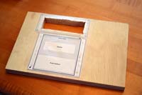 |
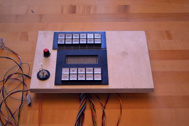
| You probably noticed how non-rectangular my holes actually are! This is why I highly recommend buying the optional metal bezels that are made for the control boards. Here, in this view that shows a test fitting of the components to the plywood board, you can see how these bezels cover up all my mistakes very nicely! Notice I have relocated the on/off key switch to this board too. I had originally intended to place this drawer on the right side of the console. Unfortunately, the cables that shipped with the control boards were not long enough for this. I decided that rather than building extension cables, I would mount the drawer on the left of the console. This necessitated moving the keyswitch - which would otherwise have been blocked by the drawer! The additional dial above the keyswitch is a knob for adjusting the reiteration rate of the tuned percussion stops. |
 |
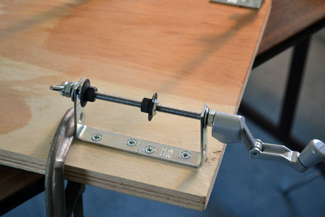
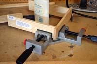
| A drawer must be built "square" (rectangular, actually). Otherwise, it will bind or simply not move at all. Hence I purchased joiner's right angle clamp. This holds pieces at a precise right angle allowing you to glue and nail the pieces correctly. This is very important so don't skimp on this step. |
 |
| Here you see the major pieces of the drawer completed. It is shown upside down on the workbench. The plywood panel is on the bottom. It is secured with screws to gusset blocks mounted on the sides of the drawer. Additional blocks are used to mount the removable bottom plate which I fabricated from some leftover masonite. I made the front of the draw wider than the sides to hide the drawer hanging hardware a bit. |
 |
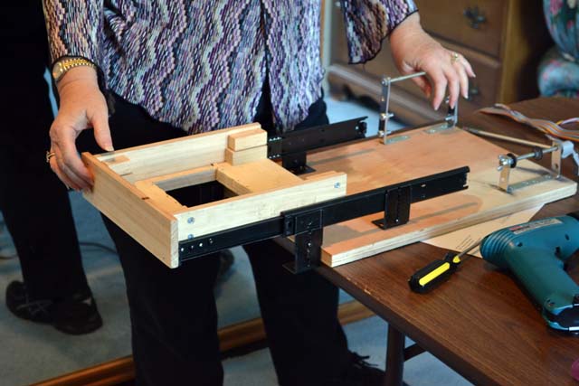
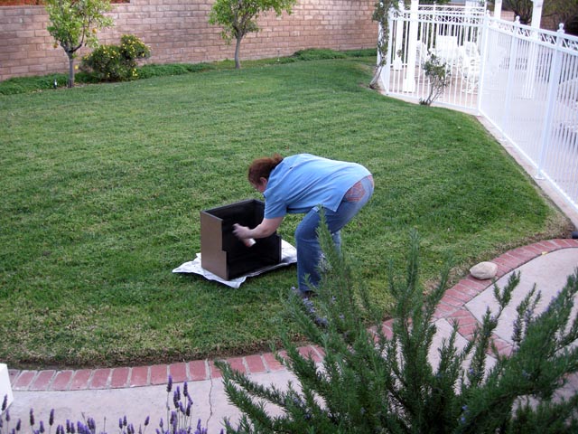
| Here is Karen testing the drawer. I have mounted it upside down to a spare piece of plywood in the "lab." Notice I am actually reusing the jig we constructed for winding spools of wire! In fact, Karen also used this same board to test the stain formula before staining the drawer (see below.) The drawer hangers are designed for mounting computer keyboard drawers under desks - a perfect analog for this organ application. Most drawer hardware mounts to the sides of cabinets and would be much more difficult to use in this situation. |
 |
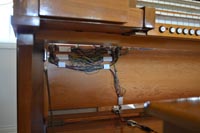
| Here is the drawer installed under the left side of the console. All the components are mounted so they can be easily removed for servicing. Notice that I even added some MASCON connectors to the keyswitch and reit rate potentiometer. I tied all the cables into a single bundle using a generous supply of cable ties. These are anchored to the back of the drawer using some old plastic cable clamps. The cable then hangs in a small loop in the two-inch space behind the drawer and in front of the console fall board. This provides the slick needed to open and close the drawer. Don't forget this step or the drawer will only last for one use! The other end of the cable is routed through the console to the Classic controller box. |
 |
| Here is the completed drawer. I used some half-round molding to dress up the seam between the plywood panel and the drawer sides. This was necessary because the panel was actually a bit off square. I think it looks better this way anyway. It has the added advantage that when sitting upside down on the workbench, the molding keeps the buttons from contacting the surface. Here you can also see that Karen did a great job matching the console color. Of course, I intend to have the console refinished later - but by this time I may also have the updated controller with the wireless controls. |
 |
| Here is the completed drawer in the context of the entire console. It looks pretty good. It has to hang a couple inches lower than I would have liked in order to clear a major structural wooden beam that holds the console together under the keyboards. Other than this, it looks quite professional. |
 |
|
Wednesday, August 3, 2011 – SAMS are all wired - and nearly all working
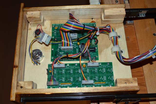
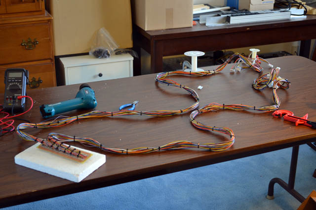
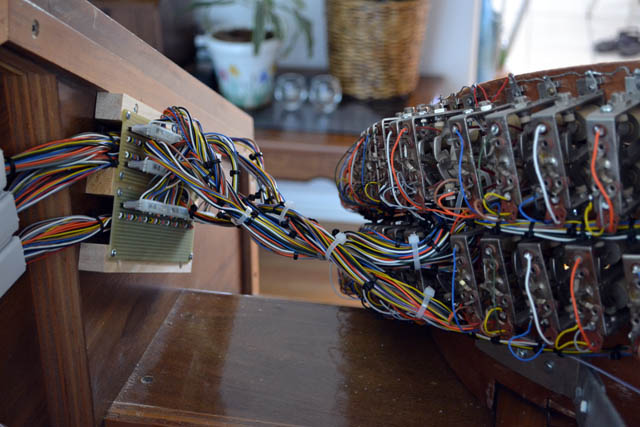
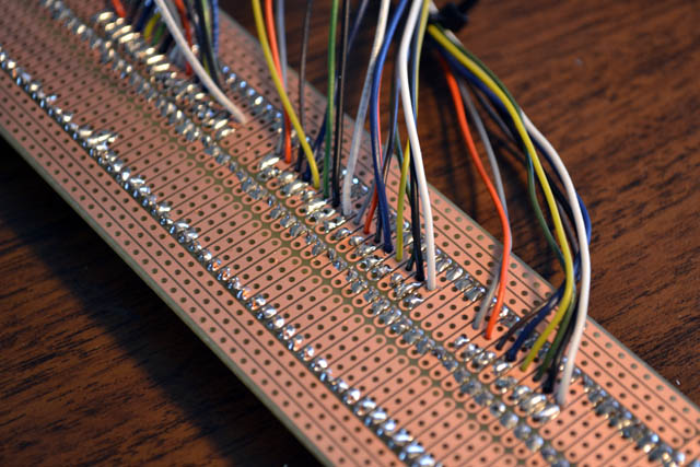
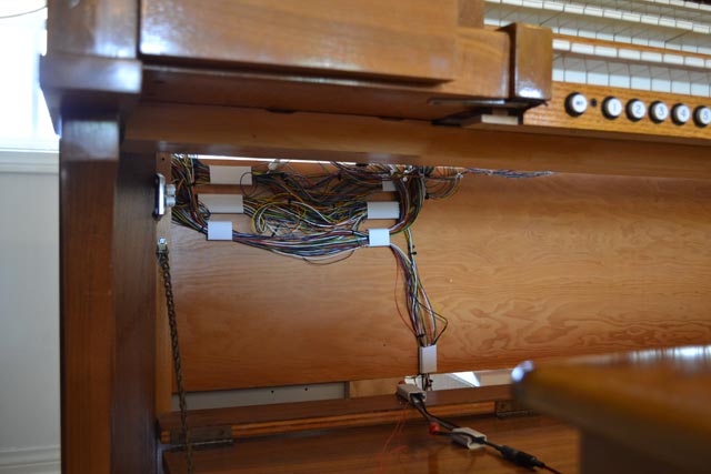
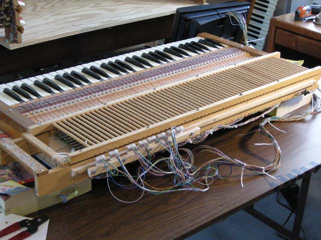
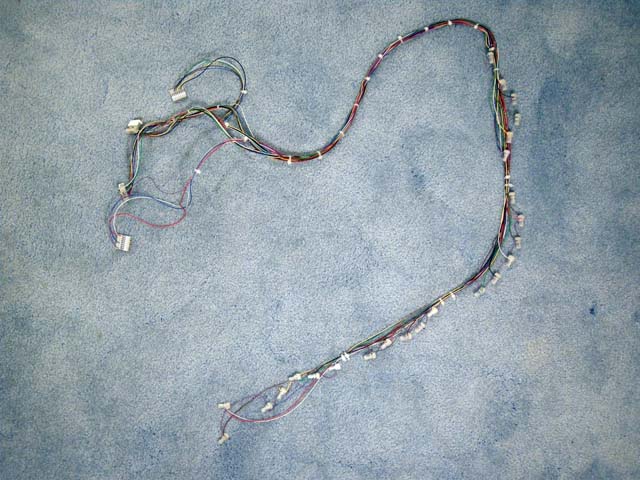
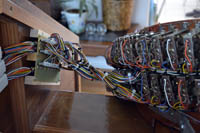
| Based on the success of the first third of the bolster wiring, I continued with the other 2/3. Here you see one of the cable assemblies that connect the bolster to the console controller. The ~100 wires are tied into two cables. Each wire is soldered to the small circuit board that also contains two rows of headers to receive the connectors from the bolster. I clamped the two plastic wire spools to the table to allow me to assemble the cables on my six foot table, even though the cables range up to 12 feet long. |
 |
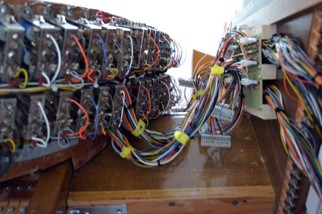
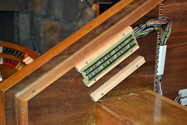
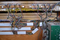
| Here you see two of the six bolster cable assemblies installed. Two of these go to the left of the bolster, two to the right, and these two in the center back of the console. The cables leaving these boards are routed to the console controller. |
 |
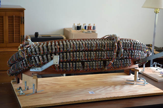
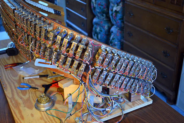
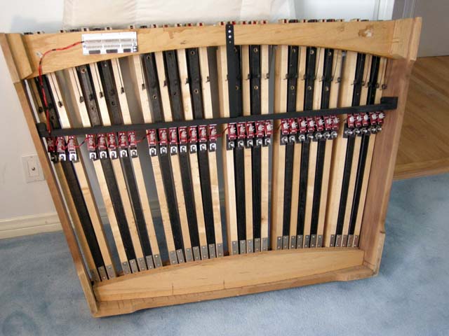
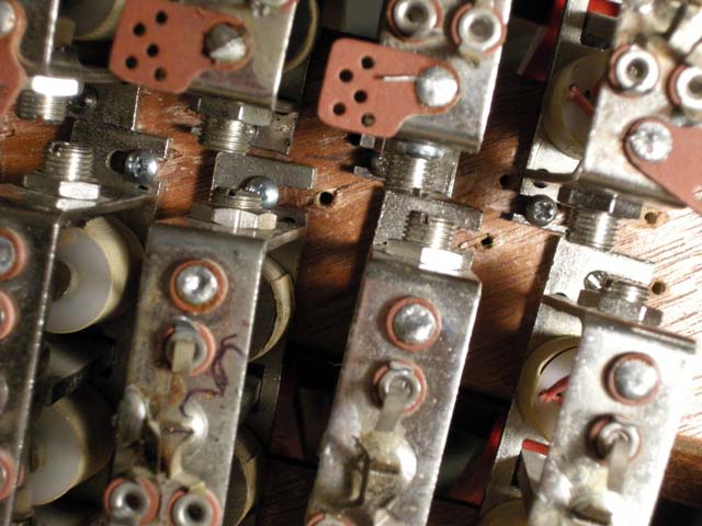
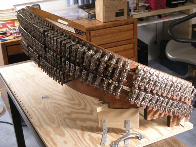
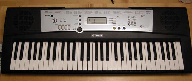
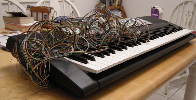
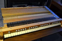
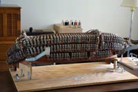
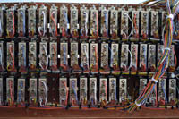
| With the cable assemblies in place, all that was left was to complete the wiring to the SAMs. Here is the bolster assembly sitting on its cradle and fully wired.This was a very big job. After wiring, I used the cheap Yamaha synthesizer to test the Reisner SAM switches, which I had carefully bent into reasonable positions. I "played" the stop tabs and isolated ciphers (switches stuck in the "on" position") and tabs that did not make good contact. The last step was to retest all the magnet coils to make sure they all still had the required 28 ohm impedance. |
 |
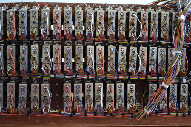
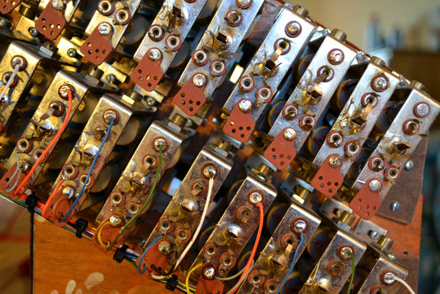
| Here is a close-up of the SAM wiring. Sometime during the wiring, I realized I had a problem with the method I was planning to use to isolate the SAMs into groups of less than 28 to attach to the 12 VDC drivers in the controller. I had created groups of this size that had their commons wired together - but then I saw that consecutive rows of SAMs sometimes were so close that they touched. Since the commons are wired to the chassis of the SAMs, this defeated the isolation! I rethought the groupings and made changes. You can see some of this here. Look carefully and you will see places where I have cut the bare wire that connects the SAMs in horizontal rows. In addition, you will see occasional red wires (I used red for 12 V lines) running between the rows. By the way, this photo would make a great jigsaw puzzle! |
 |
| Karen and I carefully moved the bolster assembly back into the console - without bending any SAMs switches! Here you see the left bolster cables plugged into the connector boards. |
 |
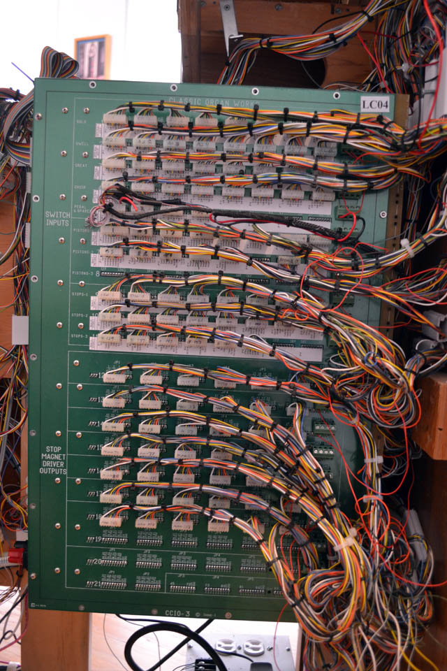
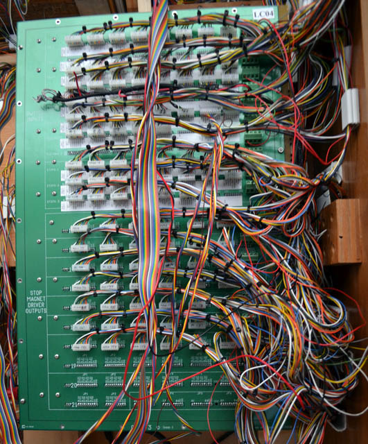
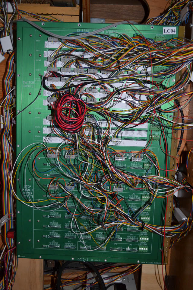
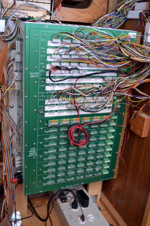
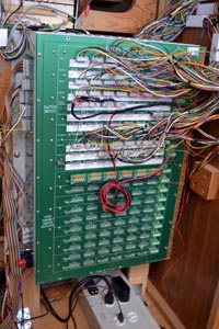
| The controller is getting full. At this point, all the wiring is complete to the connector with the exception of the accompaniment second touch contacts - which I have not yet built. These will go to the row of empty headers near the top of the controller. The bottom three rows of the controller contain no electronics - which means Classic uses this controller type for organs with even more SAMs than mine! The cables that exit the controller vertically in this photo are the ones connecting the Classic display. I will reroute these in a more logical place later. |
|
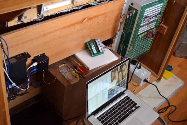
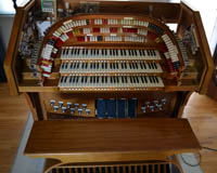
| This is a good overall photo of the organ as it stands today. The cover is removed so I can continue to track down problems with the SAM wiring. I am pleased to report that, as of now, 158 of the 165 SAMs are working properly. Most of the errant ones are tongue transplant patients - so I will have to either work on them a bit more or simply replace them with spares. I have more than enough spares to get the rest working if need be. Notice how I have mounted the Classic controller display to a handy piece of 1x1 lumber so I can reach it while sitting at the console. This is also a good view of the connections between the bolster and the console. I can remove all the bolster cables in less than a minute when the bolster needs to be serviced. I have also wired all the stop tabs to Hauptwerk so that the organ actually plays like an organ - without the need for a computer touch-screen and without undue reliance on the pistons. |
 |
|
|
Tuesday, June 28, 2011 – Its been exactly two years - and a lot of progress in the last couple months!
It has now been two years since the day we moved this theater organ console into our home. Today (or actually two days ago) we had a playable organ. I decided to record a tune on the organ before dismantling it to work on the bolster wiring. Here is "High Hat", a novelty tune by Louis Alter. He is much better known for composing "Do You Know What it Means to Miss New Orleans?" However, "HIgh Hat" is pretty well-known in theater organ circles because the great organist Jesse Crawford made a recording of it when it was new. It is a difficult piece and demonstrates that I have successfully adjusted the keyboards!
When I decided to start this project, I gave myself a budget and schedule. So far, I am still under budget - but now that I have bought most of the controller, I am getting a lot closer to my cap! My schedule was to complete the project within two years. Clearly I am running late. Of course, much of the delay was caused by the controller not being ready when expected - resulting in a very slow year last year on the project. I am certainly happy with the progress since the controller was delivered - so I will press on.
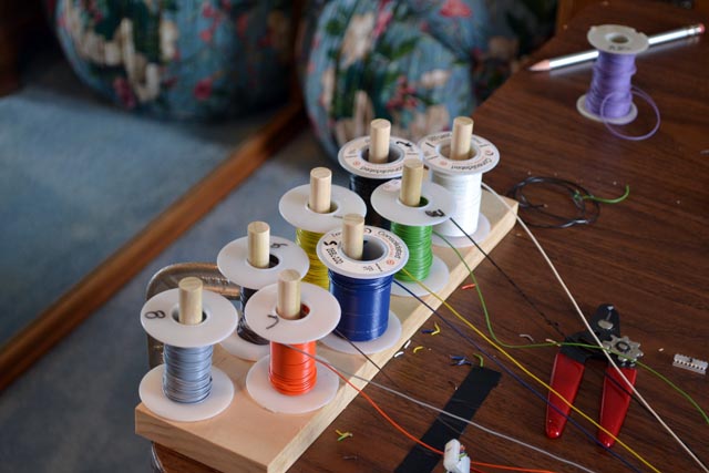
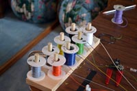
Now, back to the bolster wiring. I calculated the amount of 26 gauge wire I needed to complete the console - about 6,000 feet. Since I didn't want to waste money buying wire in measly 100-foot rolls, I bout eight 1,000 rolls, 1,000 feet in each of the eight colors I use in my cables. However, I still wanted to use the dispenser I built for smaller rolls. Hence I needed a way to get wire off the 1,000-foot spools and onto something more manageable. Karen and I built a jig to do this. This photo shows a crank assembly into which we can clamp an empty small spool. We used a threaded rod and a crank made for window casings. The trick was using these two tapered washer/nuts. They clamp against the spools and hold them tight and centered on the rod. |
 |
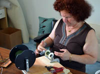
| Here is Karen loading wire onto a small spool. The large spool is on a second threaded rod and is free to spin. As you crank the small spool, you have to feed the wire horizontally on the little spool. I calculate that we get about 200 feet of wire onto these small spools. The small spools, by the way, are left over from the wire I have already used on the project. The entire spool winding jig cost about $20 in parts, including lots of leftover screws, washers, and nuts that I can use elsewhere. |
 |
| Although I could certainly wire the 165 SAMs on the bolster directly to connectors on the Classic controller, this would be silly. In order to disconnect the bolster later I would have to remove dozens of connectors and reroute all the cables. Instead, I decided to build connector boards close to the bolster. Three of these, located to the left, right, and in back of the bolster, will allow short, removable cable connections. The bolster will still be hard to remove (because it is heavy!) but at least the wiring won't get in the way. I purchased several circuit boards from my local electronics store. These have the same "pin-outs" as standard prototyping boards. I soldered headers (pins that connect to the MASCON connectors and mount on circuit boards) to the boards and then soldered wires to connect to each pin. The other end of these wires have 8-pin MASCON connectors for plugging into the Classic controller. |
 |
| Here is the first of these boards mounted to the console. Though there are three rows of pins, the center is not wired. I discovered that there was not enough room on the small board to handle that many wires! You can already see the space for mounting a second circuit board directly below the first. It will have a third row of pins to replace the unused one on the upper board. |
 |
Here is the controller. It is getting pretty crowded with connectors! When it is more complete, I will neaten things up with more cable ties.
I will complete the lower circuit board for the left side connectors and then move on to wiring the corresponding SAMs. In a few weeks, I should have some stop tabs working. |
 |
|
Saturday, June 4, 2011 – The public premier and a theater organ that surpasses my Rodgers - finally!
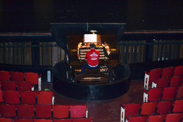
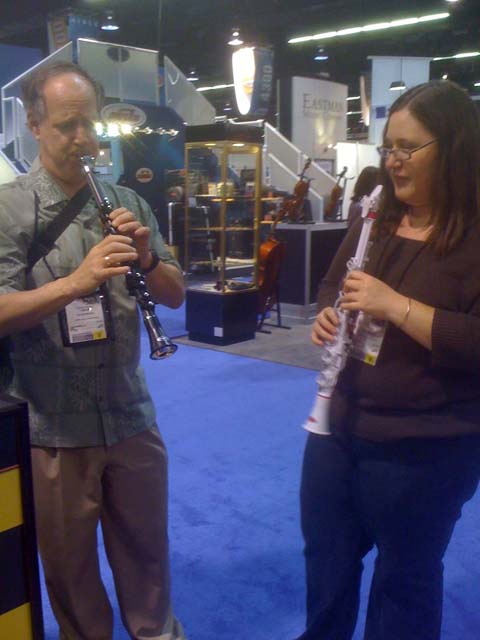
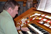
| Last Monday was Memorial Day - the first one in decades that I have not spent in Sacramento performing at the world's biggest jazz festival. The Night Blooming Jazzmen were inexplicably not invited this year! As partial compensation, Karen and I threw a barbecue at our home and invited a couple bands to play. Since the theater organ was just barely playable, I used the occasion to demonstrate it. Because the accompaniment manual had too many sticking or intermittant notes, I used the solo keyboard as the accompaniment. I got an octave and a half of the accompaniment working near the top of the keyboard and I made this the solo for the day. I had to disable the bottom four keys on the great too! I programmed most of the pistons to use Hauptwerk and a few became toggle stop tabs. I played a couple tunes and then turned the console over to Ken Rosen, who had given me the console two years ago. Here you can see him taking the organ for a spin. It took a while for Ken to get used to the top manual being the accompaniment. Also, Ken has a much harder touch than I and this resulted in some interesting bad contact problems! Cory Edelman, another theater organist, was also at the BBQ and played the organ for a while. |
 |
| I spent most of the next week in the DC area but I got right back to the organ when I returned Friday night. Here is the instrument early Saturday morning. Karen helped me take it apart so I could readjust the keyboards and get them all working properly. |
 |
| I took each keyboard back to my "lab" and carefully adjusted every key so they would turn "on" at the proper point in their travel. I used the cheap Yamaha keyboard as my test tool. I started with that stubborn accompaniment keyboard. To my surprise, it wasn't all that bad. I did a careful adjustment and then returned it to the console. I plugged in its connectors and tried it out. It was perfect. I then did the same with the great manual and reinstalled it in the console too. |
 |
| To my surprise, the accompaniment reverted to its intermittent and stuck notes! Clearly there was a mechanical interaction between the two keyboards. With Karen's help, I watched carefully as we swung the great up and down to see how it contacted the accompaniment assembly. As it closed, it put pressure on the accompaniment contact box on the rear of the assembly, causing it to bend slightly. This, in turn, caused the "on" point for the keys to change, making them come on too quickly. Indeed, many were now on all the time. I took the accompaniment back to the lab and studied it carefully. Someone had remounted the contact box on spacers to lift it slightly. I removed these and secured it as firmly as I could to the metal frame that holds it to the key cheeks. I then readjusted all the keys. I reinstalled both keyboards in the console. It was not perfect, but it was much better. With the two in place, I continued to adjust the accompaniment keys until it took pressure from both arms to cause a new failure. I will need to further stiffen the accompaniment - but I also need to figure out how to do this. |
 |
| I left the bolster assembly out of the console so I can begin work on wiring over the coming weeks. All the keyboards now work correctly. I can still cause notes on the accompaniment to come on by applying a great deal of pressure to other keys - but this is unlikely in standard playing. In fact, in the last 24 hours, I have not gotten a single failure in normal playing. The theater console now makes a better theater organ than my Rodgers 945, for the first time. All the keyboards and pedals work, plus it has many more pistons and an extra swell shoe. I will continue to play on it looking for any problems. In the meantime, I have some new ideas on how to wire the bolster... |
 |
|
Saturday, May 28, 2011 – What a difference a week makes
| It was quite a busy week at work - but I couldn't wait to return home and work on the organ again. There s plenty to do now. I bought another 1,600 feet of 26 gauge wire and 500 cable ties. Karen and I built a jig to hold eight colors of wire for making cables. We need lots of cables! |
 |
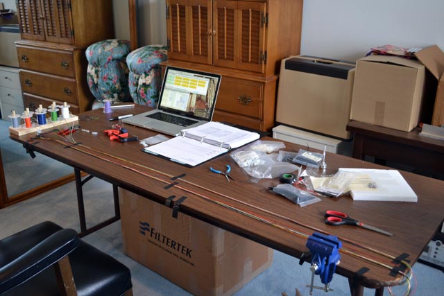
| I used the long table in my "lab" to stretch the cables, secure the MASCON connectors on each end, and finish off with cable ties. The laptop shows the wiring diagrams for the units I had completed before: the three manuals, sets of toe studs, expression pedals ... The open notebook is the documentation I received from Classic. It shows the expected cable makeup to each set of pins on the Console Controller. |
 |
Here is said console controller - getting full of cables. All the cables on the main panel have to exit to the right so that the controller can hinge open for servicing. I wired up each keyboard first. I discovered that the accompaniment keyboard has many stuck and intermittent notes. It is unusable for the moment, so I disconnected its voltage line to keep it from playing until I can take the organ apart and work on it. The Great and Solo keyboards were much better. Each has a few sticky keys - but they basically work.
I used a special feature of the controller that allows one to test the pistons and toe studs without having them try to fire off the SAMs. After verifying that each works and is wired correctly, I moved these cables from the piston section of the controller to the stop section In this way, they will generate MIDI signals I can use to connect to Hauptwerk's own combination action. My stops wont move but I can change registrations a bit.
I wired up the four expression pedals (including the crescendo). The crescendo works for a few minutes and then stopped completely. I discovered that the Klann potentiometer rack I had installed actually cut one of the wires when it moved! I repaired the wire and then cable tied it to a safer place. |
 |
| Here you can see most of the wiring for the Accompaniment and Great keyboards. The white cable clamps are actually inexpensive plastic conduit that is used to route lamp wires along walls. It has a strong adhesive along the pack for mounting to surfaces. It is molded to snap open and closed to allow easy access for wires. You can buy this stuff at any home improvement store for about $12 per five foot length. This is enough material to make dozens of small clamps. |
 |
| Many cables had to be routed behind the controller box because of the aforementioned fact that the cables had to exit to the right of the box. I passed these over the plywood and into the cavity that used to hold analog oscillators in the original organ. The fall board the holds the key switch and pedal lights folds up to hide this. |
 |
| This evening, I programmed Hauptwerk to recognize the top two manuals, all the pistons, the effects toe studs, and the swell pedals. I even programmed the accompaniment pistons as extra toggle-type stop controls for some important (loud) stops like the posthorn, xylophone, and glock. I could then play the organ. Granted - its really now a two-manual organ that has limited stop control - but I can really play it. Click on this photo to watch a movie of me playing a chorus of the old 20s tune "Turkish Towel". |
 |
|
Sunday, May 22, 2011 – The Classic controller and the organ starts to play!
This has been a very busy weekend. I was in Washington DC on Wednesday when the shipment arrived from Classic Organ Works with all the console controller components. I flew back to Los Angeles on Thursday but I went straight to UCLA with my daughter to see a musical. I did not see the box from Classic until almost midnight.
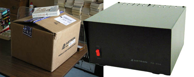
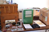
I woke early on Friday and unpacked the box. Here you can see the various units. The tall green box is the console controller itself. The low gray box with electrical outlets is the AC Controller. The Black box to the front eight is actually not from Classic - it is a five-port MIDI interface I purchased last week from MOTU.
The notebook is full of documentation. I'll have to read it soon.
That was all I could do today because ,my daughter, Erica, was graduating from Pepperdine Law School. I had to leave to go to the commencement exercises, followed by various social get-togethers.
I found just enough spare time in the afternoon to place the AC COntrol Unit in the console and wire it up to the key switch and console lights. I can now turn on the switch and see the console light up. |
 |
Now it is Saturday and I can finally concentrate on the controller. I skimmed the documentation, paying careful attention to the various block diagrams and cabling descriptions. I set up everything on the table in my "lab" where I could reach things more easily than in the console. Karen helped me move the pedalboard into the lab. Since I installed new Peterson contacts on the pedals, I knew these would work well and make a good test platform.
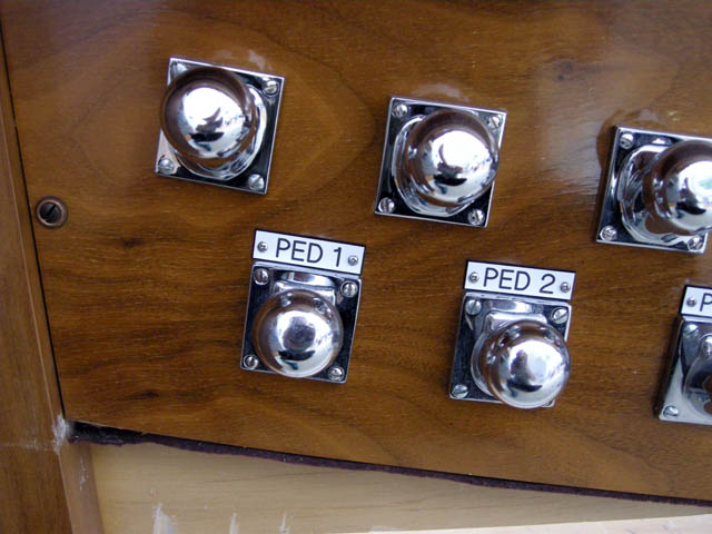
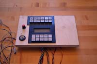
Here you see how I cabled the pedalboard to the controller. You can also see the cables from the "CRTL-3", a numeric keypad with character display that will be used to control the Classic system. Finally, I build an ersatz stop tab by wiring a small MASCON connector to a handy +12V terminal on the controller. I can use this to turn stops "on" for testing. |
 |
I connected the giant 70W Astron power supply to the controller and turned it on. At first, things behaved strangely. I wrote an email message to Classic with questions - but I also studied things much more carefully and discovered that several cables were attached backwards. I had taken a description in the documentation too literally, I suppose. In ay case, I traced the wires back from their connectors on the interior of the controller and found the error. With the cables now in properly, I turned on the system again.
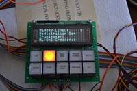
Here you see the CRTL-3 unit responding properly. |
 |
| I set up my laptop and ran MIDI monitoring software and a simple software synthesizer. Within a minute or so, I had the pedals playing! I then switched over to Hauptwerk and programmed two theater organ ranks to connect properly to the pedalboard and to the ersatz stop tabs. I could now select stops (using the MASCON connector) and play the pedals with my hands. |
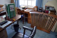 |
That was quite enough for Saturday. I woke Sunday and began mounting the Classic components in the organ console. I chose to place the Controller on the low-note side of the console so that I could still swing it open to access the interior for servicing. There is plenty of room to reach all the pins. I mounted the AC Control Unit underneath so that the power cord can exit the console easily. I mounted the MIDI interface and Classic MIDI terminal box ion the high-note side to allow easy access to a computer set up to the right of the organist. The Astron power supply is directly underneath.
I replaced the pedalboard and hooked everything together. |
 |
Erica, our new Juris Doctor, testing the organ for me. She turned on the key switch and played the pedals.
It is a but less than two years since I started this project. Now I can see a clear path to getting the organ fully functional. It will now take a lot of wiring and testing. |
 |
|
Sunday, May 1, 2011 – A Needed Switch
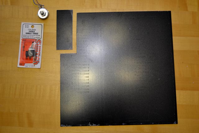
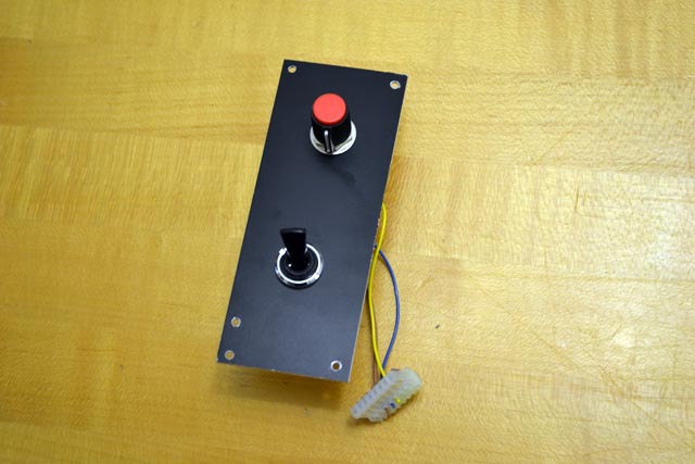
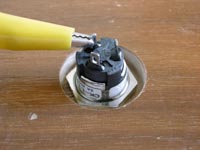
The control box from Classic will be coming with their AC Control Unit (ACCU). This is a box that manages all the AC power in the console. It allows a single on-off switch to control all the various individual power devices - including the SAM power supply, the console lights, the console controller (gray box), and amplifies. I have a problem: I do not have an on-off switch on the console! This should have been easy to remedy - just purchase one and install it. However, this was not actually trivial. All reasonable electrical switches are made to mount on either circuit boards or panels that are less than 1/4" thick. Every part of my console is made of wood at least 3/4" thick!
The solution is to bore out the reverse side of the wood to make a small area thin enough to accept a switch. With this in mind, I set off to purchase a key switch. I looked on line and found a a local electronics supply house with a good selection. I stopped by after work and discovered all the switches they had allowed the key to be removed only in the switch's "on" position! This would not work for me and I wonder why this is the norm. I purchased an SPDT switch that allowed the key to be removed in both positions. It had the longest threaded shank too - 3/4".
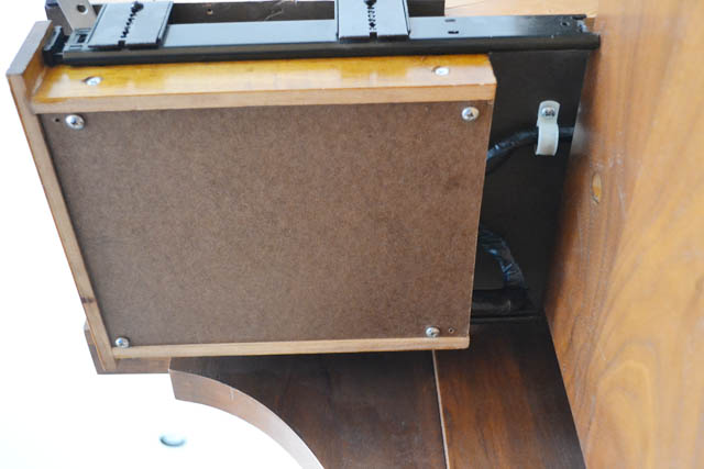
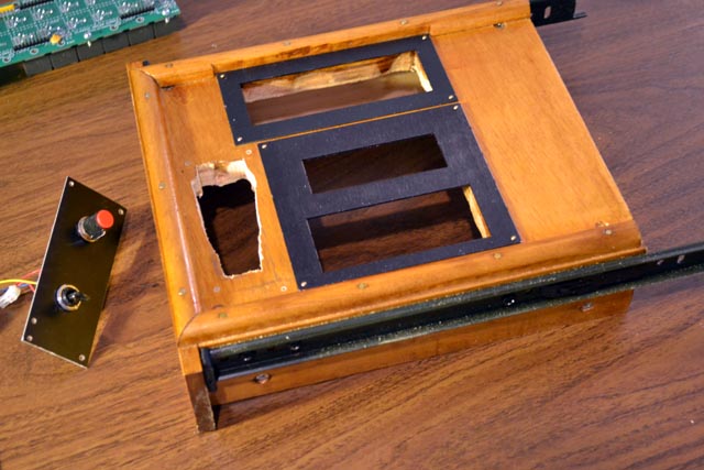
I had wanted to mount the switch on the bolster - but the thought of boring against the curved surface worried me. If I damaged the bolster I would have a hard time replacing it. I went to "plan B" and decided to mount the switch on the fall board. Here you can see how I created the bore on the reverse side of the board. |
 |
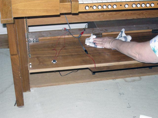
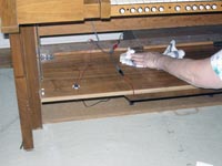
| With the switch in place, I remounted the fall board on the console. This required Karen's assistance. Here you see Karen dusting a bit before we close up the fall board once again. |
 |
| Here is the on-off switch in its new home. It is an easy reach for the organist. Now when all the equipment arrives from Classic in a week or so, I will be able to switch it on! |
 |
|
Wednesday, April 14, 2011 – A Visit from Henry Wemekamp
It has been a while since I have worked on the theater organ project. I have come to a point where I really need to wire up the console to its controller for the next steps. My plan has always been to use a controller from Classic Organ Works. They have a product that is a perfect match for projects like this in their catalog. Referred to by their engineers as the "gray box", this assembly takes inputs from all the keys, stops, and pistons on the console and provides the combination action and MIDI translation required to interface to an external computer for tone generation - including drivers for a huge number of SAMs. Before I started this project, I contacted Classic and ended up talking with Henry Wemekamp, the owner and president. Henry's idea was to use this theater organ project as a test case for next generation controller they were about to start developing. Unfortunately, various factors, including the economic recession, have delayed the work on the new system longer than any of us would have predicted back then.
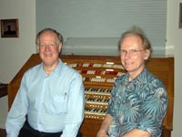
Henry and his wife Norma were on vacation this week in the Los Angeles area and they visited Karen and I last night. Here is a photo of the two of us at the console. We had a great time sharing stories with one another about how we ended up working with organs - and also discussing the pros and cons of various types of digital cameras. We also agreed on a near-term course of action for the project. Classic will ship a current model of the controller so that I can move on with the project. Since the new model will be built in the same physical chassis and have the same pin connections to the organ controls, I will be able to switch easily to the new model when it is available.
By the way, Classic is now advertising for a software engineer who will be a key person on the controller design effort. If any reader is interested in this, please visit Classic's Job Openings site. |
 |
|
Thursday, August 19, 2010 – Lights!
| I am still waiting for Classic's "Grey Box". In the meantime, I moved on to another small loose end for my project – console lights. I had decided a while ago to use this as an opportunity to learn about solid state lighting. After all, with all the power I will be wasting energizing those 165 pairs of magnets, the least I can do for the environment is to make the lights efficient! I did a bit of Internet research and came up with a company called "The LED Light Inc" at TheLEDLight.com. They sell nifty flexible LED strips. They come in 16 foot rolls or you can purchase them by the foot. I ordered six feet of the strip, along with a couple of 12 volt transformers for power and a dozen individually-packaged white LED bulbs. I ordered everything in "bright white". The strips are easy to use. You can cut them to the length you need (cutting points are every three inches along the strip) and use a handy edge connecter (purchased separately - I ordered four of these) to connect them to a 12 V supply. Here you see my strip lying on my workspace and connected to power for a test. The LEDs are very bright. |
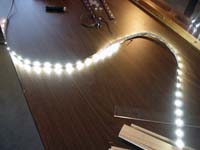 |
| I opened the Rodgers music rack by removing the two plastic translucent covers. I then removed all the incandescent bulb and and sockets. You can actually see them lying above the LED strip in the previous photo. For fun, I checked all the bulbs and found all but one to still work! That's pretty good. I saved them for use with future projects. I fabricated a pair of wooden inserts to fit into the two cavities in the rack. I used a 11" strip of 1" molding as the core and added four lengths of 1/4" square wood (from a local hobby shop that sells model railroad scratch building supplies) to create an H-girder shape. Karen painted these a dark brown. Their finish is not critical but they should be dark. I then cut a two foot length of LED strip for each of these. Each strip was stuck to both sides of the H girder by curving it around one of the ends. I attached the edge connectors to provide power. In this photo, you can see one of the girders in place. You can make out the edge connector on the left and see its wires passing under the center of the rack to the second cavity. The second girder is shown before the LED strip was attached. The second girder required two edge connectors: one to connect with the first girder and the second to connect to the console power supply. I used RCA connectors to hook everything together. They are easy to solder to, provide definite polarity (remember, LEDs are diodes so they care about which terminal is positive!), and I have plenty of old cables I can use to provide the interconnections within the console. |
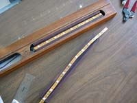 |
| The console lid had seven light bulbs in grooves that provided illumination for the stop tabs on the bolster. Since the music rack I am using provides light both upwards and downwards, most of the stops would get light from the rack. I decided to place lighting in the four console lid slots along to two ends of the bolster only. In order to make installation easy, I also decided to reuse the light sockets. Here you can see how I did this. I simply soldered an LED bulb over the old sockets. I first covered the socket with electrical tape so as not to short out the connections. Again, you have to worry about the polarity of the connections, so you must be careful. The LEDs I chose for this are 3V, so I connected all four of them in series before hooking them to my 12V transformer. My first try failed because I had one bulb soldered in backwards! I guess I was working too late at night. |
 |
| Here you can see the console lid bulbs installed and working on the bench. I reused the grooves already in place for the wiring. This meant I did not need to borrow a router again. |
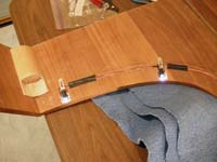 |
| I also wanted to provide lighting for the pedalboard, expression pedals, and toe studs. I fabricated this wooden bracket from a length of L-shaped molding with a piece of 1/4" quarter round molding attached as a lip. I also mitered the ends for a more pleasing effect. Karen stained the assemble to a dark walnut to match the eventual console finish. I installed a two-foot length of LED strip and an edge connector to finish the job. The assembly is screwed into the fall board. |
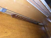 |
The overall result is excellent. Here is a photo of the console in the dark. The new solid state lights are providing all the illumination. The music rack provides plenty of light for reading sheet music. The stop rails are nicely lit (in large versions of these photos, you can read every stop name). The pedal light does a great job on everything beneath the lower manual.
The console looks great - but it still doesn't play anything! Hopefully that will be remedied soon. |
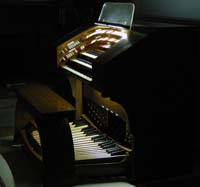 |
|
Tuesday, June 8, 2010 – Adding a music rack
I am still waiting for the "grey box." I decided to add a music rack because no organ is complete without one. The original music rack from the Artisan console is missing. Ken Rosen was nice enough to give be an old Rodgers music rack when I took the console. Ken has tons of organ parts lying around in his studio and I am very happy to have this one. The rack comes from an old Rodgers 33E so it is a more modern style than a typical theater organ rack – which suites this console completely.
I removed the outer cover and carried it to my work room. I placed removable blue tape over the center and the areas that would have to be drilled attaching the music rack brackets. I carefully measured all the positions for the holes and drilled them. |
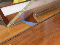 |
| I was a bit worried that the holes might come out right on top of some exiting holes in the cover. In this close up view of the underside of the horseshoe part of the cover, you can see how Artisan cut a groove for wires that connect to several small light fixtures. One fixture went in the rectanglar notch to the very left of the photograph. These seven bulbs provide light for the stop rails. I removed all the old light bulbs and wire, saving them for later just in case. Just as I expected, one hole for each music rack bracket came out right in a light bulb notch! Luckily, there is still about 1/4" of wood so I judged the strength as adequate. The second screw for each bracket goes through the entire 3/4" of the cover. By the way, the shiny material in the notch is a bit of aluminum foil Artisan placed to help direct more light downward toward the stops! |
 |
| Here you can see the brackets mounted on the console. I will no longer be able to fold the horseshoe part of the cover completely flat on top the console – and I should probably add some protective bumpers. This is a job for later. |
 |
Here is the finished music rack in place. I still need to replace the old lighting in the rack with modern solid state bulbs. Since the rack lights shine both upward and downward, they will light most of the stop rail as well. I will only need to replace the outer two stop rail bulbs on either side of the underside of the horseshoe cover to complete the lighting for the upper portion of the console.
Any of you who have been to one of my ragtime piano concerts knows that I usually play from sheet music – unlike most performers. I explain to my audience that I do this "...because I can." Now I can do this on the theater organ, when it actually starts playing of course! |
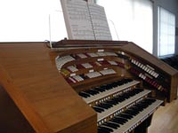 |
|
Saturday, May 15, 2010 – More console tags and an electronics lesson
Actually, the electronics lesson comes first. One of the basic equations in electronics is known as "Ohm's Law." It states that V=IR where V is voltage, I is current, and R is resistance. Since each stop action magnet (SAM) on my console has a 30 ohm coil (R) and is driven at 12V, the amount of current each will draw is V/R = 0.4 Amps. Although each SAM has two of these magnets, only one will even be engaged at a time. Hence, the largest number of coils I will ever engage at once is the total number of SAMs, or 165. Therefore, the largest possible total current the combination action will draw is 165 x 0.4 = 66 Amps.
Here you can see the 70 Amp power supply I purchased for the organ. It is so powerful that I had to order it from a company that sells amateur radio transmitters! It weighs close to 50 pounds. Mine is in that box. I unpacked it once to verify it works. Then I packed it again to wait until I need it. SInce it is too heavy to unpack unnecessarily, I included a web photo of the unpacked unit! I will mount this inside the consol - but not until after the grey box is installed and everything else is working. |
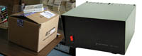 |
I want the finished console to look truly professional so I decided to add tags (labels) for the toe studs and expression pedals. I could have purchased these from Arndt - like I did for the labels I have already installed on the bolster. However, these lower tags do not have to look like Wurlitzer replicas. Many theater organs did not even have these.
I found several online sources for plastic tags like this. They care usually called "panel tags" because they are meant for labeling control panels on large electronics gear. Mine come from E. R. Perry Signs Engraving. They have an online order form. I specified the color, text,and size of each tags. I also added comments to define the font I wanted (their "normal" font") and the font size. Remember, these have to be readable from the oran bench. I chose 30 point which is the largest size that fits on the 1/2" tags I ordered.
The tags come by mail service in a few days. Mine cost about $4.00 apiece. Here is the bag of tags which arrived in a soft envelope. |
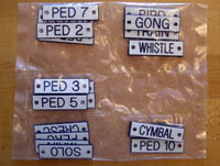 |
| I specified mounting holes for my tags. I bought small screws to match the holes I mounted the toe stud tags over each toe stud directly on the fall board as shown. The upper row is still to be installed in this photograph. |
 |
I could not mount the expression shoe tags on the fall board because the Artisan console has a hinged drop-down board that sites about two inches in front of the fall board and extends to just over the swell shoe opening. Swell tags mounted on the fall board would not be visible from the organ bench because of this. Hence I decided to mount these tags on the drop-down board.
I taped some scrap paper on the lower edge of this board and carefully marked the positions of these four tags. I then drilled the holes for them, removed the paper, and screwed them into place. |
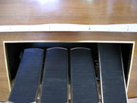 |
Here is the console with the bench removed so you can see the newly-installed tags. It definitely adds to the finished look of the console - and may even help guest organists find their way around.
I corresponded with Classic Organ Works this week. They are making good progress on their new "grey box" and I may have mine in a month or so. The really good news is they will likely replace their old control panel (for which I would have had to build a drawer in the console) with a iPad! This is so cool.. |
 |
|
Monday, March 29 2010 – Building a baffle for the expression shoes
|
Monday, March 22 2010 – A new set of pedal contacts
One of the many suggestions that Arthur Crtichley of Classic made early on was that I should consider replacing the old Artisan pedal contact assembly with contacts that are mounted directly to the pedal board. Since the Classic "Grey Box" is still in construction, I had the time to finally consider this. I also took the time to order a 70 amp 12 volt regulated power supply from Astron. It will take a month to arrive but I'm in no hurry. I need 70 amps to drive all the SAMs - and the supply weighs close to 50 pounds! I will want to mount it on the floor of the console - space now occupied by the Artisan pedal contact assembly! All the more reason to replace the pedal contacts.
I did some research online and determined that Peterson Electro-Musical Products had the best sounding pedal contact system for retrofitting an existing AGO pedal board. I sent an email message to the contact address on their web site and Scott Peterson himself responded. Scott is the son of late company founder Richard Peterson, who invented (among other things) the Peterson Tuner which is the gold standard in the organ industry.
Scott showed a keen interest in my project and in helping me in any way he could. Perhaps it is because we are both sons of important organ inventors. We corresponded for a while and I sent him photos of the pedal board and manuals (I am still looking for an easier way to implement second touch). He actually asked one of his designers to help – before I had spent a dime. They sent me a full size drawing of a crosspiece to be mounted under the pedal keys. I transferred the drawing to a piece of foam board. Here you see Karen helping me fit it to the pedal board. I sent a modified drawing back to Scott indicating the changes needed to make it fit. |
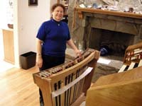 |
| A couple weeks later I received the wooden crosspiece and a box of Peterson pedal contacts and cables. They fabricated the crosspiece for me at a very low additional cost - and even supplied pre-drilled mounting cleats and screws – and it was already painted black! Here you can see the piece installed on my pedal board. The Peterson kit comes with this metal drilling template. I used it to mark the location of the 64 mounting holes. My drill press made quick work of the holes and a hand drill helped install the contacts. |
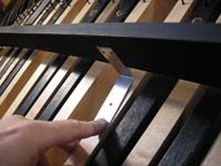 |
| Here is a Peterson pedal contact. It mounts to the crosspiece and the plastic bulb abuts the bottom of a pedal key. As the key is depressed, a magnet on the back of the medal blade swings toward a magnetic reed switch mounted on the small red circuit board. In this way, the only thing that gets connected to the keys are short pieces of felt that eliminate any clicking sound. |
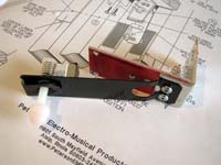 |
| Here you can see all the contacts mounted to the crosspiece. The kit came with a cable that mounts (without any soldering) to connectors on the individual circuit boards. You can see that it is connected to a junction board at the top (in the photo) of the pedal board. A second harness (also provided) will connect this to the organ and provides a quick disconnect for removing the pedal board. The biggest surprise for me was that Peterson included an inline contact tester on the junction board! There is a set of 32 LEDs and a pair of power terminals. I clip leaded a 9-volt battery to the terminals and brought the system to life. Depressing a pedal key lights one of the diodes - assuming the contact is properly adjusted. A plastic screw on each contact is used to adjust the switch closure point relative to the key throw. I adjusted all the keys to make contact at approximately the 50% throw point in under five minutes! The Peterson system is a class act. They provided all the screws and felts - with extras - and a good set of instructions. The entire job took less than three hours of total work - and it all worked the very first time. |
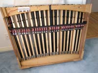 |
|
Tuesday, February 16 2010 – New home and new pots
| Progress continues at a slow pace while the master bedroom rebuilding nears completion. Here is a photo of the console sitting in our family room. This is the room it will likely occupy when it is complete. The room is 30' long, has a 16' pitched ceiling, and has hardwood floors. Today, the console sits atop pieces of the old master suite carpeting to protect the wood floor during work. |
 |
| I took advantage of the lull in activity to revisit the sostenuto switch. When I received the part, I did not see an easy way to attach it to the expression pedal (it goes on the left most expression pedal.) The problem is that my expression pedals have a stamped metal edge that creates an outline groove. The mounting screws for the switch cannot go in this grove - but instead must sit about 3/8" inside the pedal's surface. We had to pull the rubber tread back to expose the metal and drill the holes. The rubber will be cemented back in place - but only after I prove to myself that this is completely working! |
 |
| Here is a view of the bottom of the expression pedal. I used the 1/2" metal spacer that came with the switch to mount it to the pedal. This provides about the right amount of protrusion - plenty for the foot to engage the switch. I had to cut the curved metal stamping on the expression pedal around the switch and bend the metal back on itself in order to let the switch have the proper motion. |
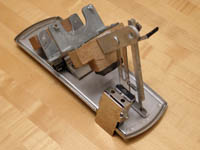 |
| When I examined the circuit diagrams from Classic, I discovered that they expect the potentiometers on the expression pedals to be 10K ohms. I wrote to Classic to find the acceptable range However, my existing 200 Ohm rheostats would simply not work! SInce I had purchased a new rack and pot assembly for the crescendo pedal, it was fine. I had to replace the three other pots. I went to a local electronics supply store and purchased three 10K ohm pots with 1/4" shafts. I had to cut the shafts down a bit so they would not interfere with the adjacent expression pedals. I then carefully removed the old pots, transferred the gears to the new ones, and installed the new pots. This was a very easy task that took only 30 minutes total. |
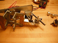 |
|
Wednesday, February 3 2010 – Project still on hold, but the music continues
Our master bedroom rebuild is about three-quarters complete now. We are still waiting for the carpeting to be delivered and installed. In the meantime, the organ console is sitting in its new home in our family room - except for the bolster assembly which is still in the lab. The center of activity for the project has shifted to Toronto where the good folks at Classic Organ Works are assembling the "Grey Box" that will convert all the keys and stops to MIDI signals and provide the coupling and combination action. They have sent me a stack of wiring diagrams(actually its a folder of pdf files). I also managed to find some 16-pin MasCon connectors that I will use to wire the bolster.
I also attended the West Coast NAMM Show. I have done this every year for the last 35 years at least. I look forward to NAMM every year. I keep up with everything that is going on in the music industry. Since I play many instruments, its also a great opportunity to sample all the new products. Here you see me playing a contrabass flute from Jupiter (the company, not the planet.) It actually DOES play - though it takes so much air that you could pass out after eight measures! |
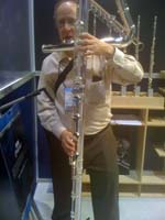 |
I contacted Classic and discovered that Darryl Wood would be attending NAMM for them. I emailed Darryl and we met at the Rodgers exhibit area. He had his lovely fiancee with him. We talked for quite a while.
Here you see my daughter, Erica, and I trying out plastic clarinets. These instruments are entirely made from plastic - including the pads, springs, and reeds! They play (in C) but play a lot better if you substitute cane reeds. I also played some very nice new tubas from Kanstul. Their demonstrator, Howard Miyata, is a colleague of mine from the Dixieland festival circuit. We played jazz duets together for a while but I did not get a photo. |
 |
| On January 30, Caltech held its big annual jazz concert. Paul Lopez was our special guest star for the evening. Paul, shown here conducting from his chair, is pretty much single handedly responsible for developing the salsa big band genre in the 40s through the 60s. He played trumpet, composed, and arranged for all the big names - even Tito Puente. I played lead tenor in the concert, and my son, Elliot, directed the student band in a chart he composed for the occasion. We had about 1,200 people in the audience - a lot for a Caltech concert. Here is a recording of the closer for the evening, Dazzle, written and conducted by Paul Lopez and featuring me on piccolo. |
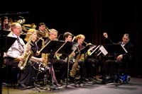 |
|
Sunday, January 3 2010 – Project on hold for bedroom repairs!
| A you could see from recent console photos, our bedroom sustained some bad water damage. It happened over the Thanksgiving holiday. Luckily, Karen was at home at the time (I was playing at a jazz festival out of town) and she was able to stop the burst water pipe in less than 30 minutes. Even so, it was enough time for the water to begin to permeate the walls and carpeting in three rooms of our house - including the master bedroom with the theater organ console. It has taken this long to settle with the insurance company, select new paint colors, carpeting, and wall paper, and hire contractors The repairs begin tomorrow and will likely last for about two weeks. We had to pack our master suite. During the repairs, Karen and I will live in our children's two rooms upstairs - since they have both moved out at this point of our lives. The organ console has its keyboards installed, but the bolster assembly is still in my work area. I see no reason to place it in the console just to make it heavier for the furniture movers! |
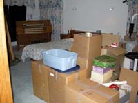 |
Here is the bolster assembly. All the knickknacks from our headboard are spending the repair period with the stop tabs. Since the organ console will be moved to our family room during the repairs, we may let it stay there afterward. I am sure the movers won't mind!
I will spend the next few weeks attempting to round up 25-pin MasCon connectors so I can wire the bolsters. At that point, I will be ready to connect to the Classic master computer - which I still need to purchase. |
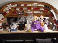 |
|
Monday, December 28 2009 – Cheek slots, piston cables, and triangles
| Though it seams a shame, we took the console apart again - including removing all the keyboards. There is still much work to be done. The bolster is stored on its stand in the work room for the moment. I took the accompaniment (bottom) manual and wired the primary key contacts. This work went very fast as Ken had done a great job on the wiring. ALl I had to do was add the MasCon connectors and test everything. I also clean the keys. This manual will have second touch - but I did not have time to install it at this point. I tried an experiment and actually temporarily installed two second touch springs to see if it would work. |
 |
Here is my plan for adding second touch. The key movement is restricted in the top of its motion by a screw that sits in an inverted channel. I have been adjusting the key height using this screw. The basic idea for the second touch springs is that they engage this screw as it is pressed below the channel. I placed a board below the key block to hold the springs (there is only thin air at the moment where the springs should be attached!) The spring is adjusted to span the bottom of the channel. I loosened the screw so that more of the key motion would engage the spring. The first thing I noticed was a metallic click when the screw hit the spring. I eliminated this by placing a small piece of felt on the spring where the screw hits it. The result was not perfect, but I can see that it WILL work with a little more adjustment. I had to remove the test so that I could proceed with the key cheek routing. |
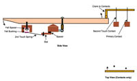 |
I still need a way to pass the piston cables to the back of the keyboard assemblies. I planned to do this by routing a slot in the inner surface of the left key cheeks. However, my attempt to do this myself using a routing bit in my drill press failed. A friend of mine from work suggested I call Paul Graetinnger, a mutual friend. I contacted Paul a month or so ago and he agreed to help me with this. I had to wait until today to have a good time to visit him. Paul has a large wood shop behind his house with every kind of tool imaginable. He set up a router on work surface and helped me create the required slots. |
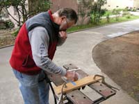 |
| We started by extending a slot on the inner surface of the key cheek from the point where it meets the piston rail all the way to the back of the cheek. We then cut all the way through the back of the cheek to give the cable an exit point. We joined the two cuts with a second channel. The result may not be pretty - but it is exactly what I needed. |
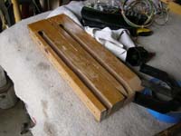 |
Here you can see the accompaniment keyboard with the piston rail and cable installed. The cable emerges near the back of the key cheek. It then passes through a pair of slots I cut into the contact assembly and goes to the rear where it terminates in MasCon connectors. I repeated this for the other two manuals. It all worked great. I tested each one before mounting them in the console. I wanted to be sure things still fit together properly.
I discovered one minor problem. The "Set" piston (leftmost on the accompaniment manual) seams to have been pushed halfway out by pressure from the cable. I'll correct this the next time that keyboard is on my workbench. |
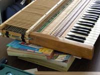 |
| Karen and I did one additional thing this weekend. I attached metal angles at the rear of each keyboard and we repositioned the metal triangular braces that hold the back of each keyboard. The original holes in the wooden keyboard frames were badly cracked and I wanted to be sure that the keyboards were mounted as solidly as possible. This also allows them to swing upward for minor servicing. |
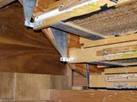 |
|
Sunday, December 20 2009 – Completed bolster assembly, test fitting,more SAMs, and virtual refinishing
| I purchased some decorative molding and cut it into small pieces that will fit between the the divisions on the bolster. I then cut small pieces of 1/2 inch square wood at the same angle as the top tabs. I glued one to each piece of molding. Karen then stained and shellacked these assemblies to match the maple color of the bolsters. |
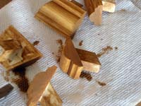 |
| Here you can see two of these "division dividers" in place on the bolster assembly, while it was still on the work bench. I fixed two small strips of brown felt behind each piece so it would not scratch the bolsters. |
 |
| The division dividers are attached to the bolsters using gusset plates I cut from masontite. Each plate has three screws. The outer screws attach the plate to the bolsters while the center, longer screw goes into the division divider assembly. I predrilled and tapped these holes so they was little change of breaking the division dividers apart during this assembly. |
 |
| I had to do one more thing before we could place the bolster assembly back into the console. SInce the console had never had SAMs all the way to the right edge of the console, the wooden brace under the right side console lid had to be carved back to provide clearance. I purchased a couple of extra long (about 12") drill buts and used my drill to bore many adjacent holes down the length of this brace. I then drilled a second set of holes down from the top to meet these. FInally, I used the drill to merge the holes together until the piece dropped out. I then finished the gouge using a grinding drill bit and some sandpaper. |
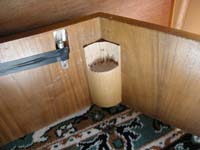 |
Karen and I carefully carried the bolster assembly, still attached to the bolster support frame, into the bedroom and placed it on our bed. It is now a lot heavier than it has been due to the mass of 165 SAMs! We then slowly moved it from the frame to the console. Although we did this with no problem, it was very hard work and I will try to minimize the number of times we have to do this for the remainder of the project.
Notice that the bedroom does not look as nice as before. A few weeks ago, while I was playing at a jazz festival in San Diego, a hot water line burst in our master bathroom. Luckily, Karen was home and the leak was stopped in about 20 minutes. This was enough time to damage the lower part of the wall in three of our rooms as well as portions of the carpets, drapes, and wallpaper. You can see the carpet cut away to in the foreground. The drapes behind the console are at a contractor for repair so some old blankets are in their place on the French doors! |
 |
| We called Ken Rosen to come by and see the console. Although it was already pretty late (around 10:30 PM) Ken stayed and talked for an hour. I returned to Ken all the stop tabs I decided not to use. I also took the required "sweep" shots of the console since this is pretty much what it will look like when it is all complete. Here is the "full sweep" photo. |
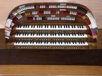 |
| Here the "left sweep" showing the pedal and accompaniment stops. You can also get a good look at the division dividers. They really add some class to the bolsters. |
 |
| Here is the "center sweep" showing the great stops and the straight rail. The round colored lights in the center of the lid were meant to be a crescendo pedal indicator system - but they were never connected! I will remove them and have the holes filled in. I also plane to replace all the incandescent lights in the console with nice, efficient sold state lights (LEDs). Its the least I can do to compensate for the fact I need enough current in the console to fire 165 magnets! |
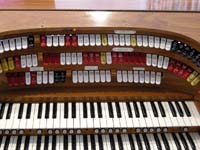 |
| Here is the "right sweep" showing the solo stops. I have used just about all the available space on the bolsters for stop tabs. I suppose I could put eight more on if I give up the division dividers ... |
 |
| Earlier in the day, Karen and I drove and hour North to Lancaster to visit Willis Chase of Chase Organ Company. Willis responded to my "want to buy" add for SAMs. He is a small manufacturer of electronic organs. He used to use the same model SAMs that I am using - but a while back he switched over to lighted push buttons for his stops. That left him with 36 Reisner SAMs still in their original boxes! These have never been used, though they are old enough to have been purchased directly from Reisner. I bought the entire lot. By the way, Willis has quite an exotic inventory of organs, organ parts, and old electronic equipment. He has no web site, but interested people should call Chase Organ Company at (661) 433-7471. He is getting ready to retire so you could even buy his company! We had a great time telling each other stories from the organ business. |
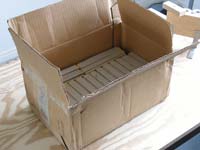 |
| This is what Reisner SAMs look like in their original packages. They came two to a box. These "newer" SAMs differ from my 60s and 70s SAMs in a couple ways. The most obvious is the blue wrapping around the magnets. The common magnet leads are now soldered to the sides of the armature rather than the bottom. Also, there is a plaster sleeve on the tongue where the pin goes through. I will put these SAMs in the bolster to replace the non-working ones that I emplaced as place holders. |
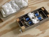 |
| Since I am fairly proficient with Photoshop, I decided to see how the completed console might actually look. FIrst, I isolated the broken bedroom background so that the console floats on a sea of black. Then I create a layer and isolated all the console parts that I intend to have refinished in darker wood. I used Photoshop's controls to re-stain these to a dark walnut. This photo is the result. |
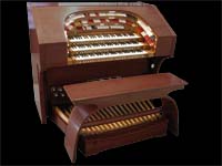 |
| Here is the console done in a glossy black finish instead. |
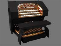 |
| And here it is in white. I can easily generate more choices. I won't actually have to decide for a few more months. |
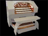 |
|
Monday, December 14 2009 – Piston cabling and lots o' SAMs on the bolsters
While waiting for the remaining 83 stop tabs to arrive from Bob Arndt, I returned to the piston rails. Now that I had the correct two terminal MasCon connectors, I assembled a cable for the pistons under the Great manual. No soldering was required! Technology progress is great. Here you see how it works. A common wire (-12V) passes through all the connectors while each piston adds a signal wire of its own to the cable. This makes 24 wires for the 23 pistons under the manual. However, one piston under each manual is lighted, requiring an additional two wires. That single four-terminal piston is serviced by two 2-terminal MasCon connectors that simply abut each other.
The wires are passed through a slot I routed into the left key cheek and then to the back of the keyboard where they terminate in four 8-terminal MasCon connectors. Unfortunately, the slot I created was not nearly deep enough and also needs to taper toward the read - something I cannot do with my drill press! |
 |
| After "playing" the pistons with my Yamaha test keyboard to make sure all the wiring works, I took the cable off to be stored until I can fund someone with a router to help me cut a better slot. Here is what the cable harness looks like by itself. |
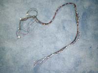 |
The Arndt stop tabs have arrived! They truly look great. I resorted both shipments into console order using the plastic packages in which they came.
When I started mounting the stop tabs in my SAMs I discovered that not all SAMs have the tongue holes in exactly the same place. I have three different batches of SAMs and each has a slightly different hole location. The three batches include the two I received from Ken plus the shipment I purchased on eBay. I did a quick accounting of the SAMs in each batch and found a way to place like SAMs in each row of each division. The spaced between the divisions will disguise the differences. |
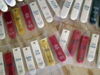 |
| The straight rail assembled trivially as before. The first bolster however had some overlap in the SAM mounting with the edges of the straight rail. I took a sharp hack saw to my precious SAMs to narrow the lower mounting edge and make them fit flush against the wood. Here you can see three SAMs with saw cuts - although these are on the second bolster in the accompaniment where they interfered with the first bolster. The SAM mounting must be precise with respect to the slots or the stop tabs will not retain full motion. I had to re-drill many SAM mounting holes to make everything line up perfectly - or at least good enough. |
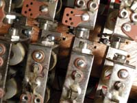 |
That's a lot of SAMs! 165 to be exact. It turns out that I accidentally counted some remaining damaged SAMs when I began this assembly - and I actually broke one SAM with an errant finger! Hence I am still seven SAMs short of a console (as they say.) I used some damaged SAMs to complete the sweeps anyway so I could be sure all the holes were drilled correctly.
Lucky for me, Willis Chase, the owner of Chase Organ Company in Lancaster, California, called me around this time to tell me he saw my "want to buy" add. He has 36 more Reisner SAMs that I can purchase. I will visit him next Saturday and buy the SAMs. This will give be enough to finish the console and have a good supply of spare SAMs. After all, the real test will come when I hook all of this to the combination action and see if the magnets will indeed move the tabs smoothly. |
 |
| Here is a photo of the completed (with a few bad SAMs) bolster assembly. I will plug the holes between the divisions with decorative molding in the near future. Then I should put this thing back in the console for some photos before continuing. I am making good progress. |
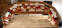 |
|
Saturday, November 21 2009 – Sam I am, and just listen to those toe studs!
While I was waiting for my SAMs, extra connectors, and stop tablets, I decided to pull out the pedal contact box and add its wiring. I started by removing the chest magnets that were used to engage the individual contact bars on the old Artisan. There were twelve of these. Since they stuck up out of the box, I could now make the box a bit smaller, leaving additional room in the console for the Classic computer system. I purchased a 8' x 4' sheet of masonite for the task. I had the folks at Lowe's cut it down to the correct size, and also cut the remainder into small enough pieces to fit in my little Mercedes wagon.
I wired the pedal contacts in the same way I did the two manual keyboards. I had to reroute all the old wiring because, for some reason, someone had looped all the wires over the lip of the wood. These wires would be pinched between the contact assembly and the bottom of the console - not a good design. |
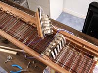 |
| I was quite surprised when a "box-o-SAMs" came to the house on Thursday - only four business days after the auction. Unfortunately, Karen did not hear the delivery and by the time I returned home from work it was too late to retrieve it from our local post office. Karen picked up the box on Friday. Here is what a box-o-SAMs looks like. It is quite heavy. |
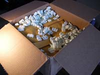 |
| I spent Friday evening testing each of the SAMs. They are all the correct tongue angle and they all work. Since there are 40, I should now have enough to complete the console, plus a small number of spares. The SAMs came with some very old classical style stop tablets. One was broken - but I have 39 of these if anyone wants to buy them from me! The organ from which they came must of been very strange. All the stops in the manuals were at 8' pitch and there were couplers of all footages (including things like 2 2/3' and 1 3/5'.) The first organ I ever played, at my parents house when I was only three, was a Conn Artist with this kind of specification. |
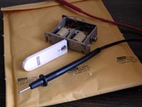 |
| Next I moved to the toe studs - specifically the ten pedal divisionals to the left of the swell shoes. When I removed one of the old ones that came with the console I discovered they were double touch. I elected to wire them as single touch pistons. Karen came up with this novel solution to holding the toe studs while I solder to the contacts. It is the end of a foam pool toy. I enlarged the exiting central hole to fit a toe stud securely. Since it is foam, it does not scratch the chrome finish - yet it holds the toe stud well enough to apply pressure with a solder gun. |
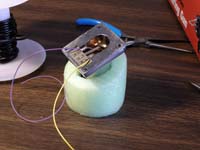 |
| Here you can see Karen installing one of the toe studs. The two wires pass through a small hole I drilled in the fall board. |
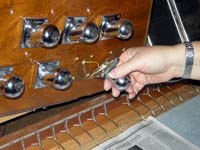 |
Here you can see the toe stud wiring on the other side of the fall board. I wired the toe studs to MasCon connectors. I then plugged them into the Yamaha test keyboard and played the toe studs! I could even play them polyphonically!
We then repositioned the pedal board and I adjusted the interface between the pedals and the pedal contact box. I had to adjust some of the brackets that are on the ends of the pedals so that they had the correct high with respect to the contact cranks. When it all worked well enough, I fastened the pedal contact assembly to the bottom of the console with steal angles. Surprisingly I could find no evidence that the assembly had ever been secured to the console in the past! When we got it from Ken, the box was simply sitting on the bottom of the console. |
 |
|
Sunday,November 15 2009 – Solo manual contacts and an eBay purchase (I hope!)
A little additional work resulted in the completion of the contact wiring for the Great. I even used my router bit in my drill press to make a groove in one of the key cheeks through which I can route the wiring from the thumb pistons. However, when I went to assemble the wiring for this I discovered that the 2-terminal MasCon connectors I had received were incorrect. They were all terminating connectors rather than through connectors. Since I need to pass the common wire through all of the these, I was stuck. I was not able to convince Online Components that they had made the error since I had waited past their 21-day return period. Hence I simply ordered the correct part (as well as a lot more connectors) and went on to the Solo keyboard.
The Solo was a lot more work than the Great. For one thing, the keyboard needed a lot of adjusting. Also, many more contact wires were broken and many fewer had good wire leads. It took several evenings of careful soldering to get it all wired.
This photo shows how I used the old wire linkages (that used to go to magnets for actuating each row of contacts) to force several rows on contacts to be permanently engaged. |
 |
| Here is view of the ends of the keys where they link to the wire cranks that, in turn, engage the many rows of contacts. Since these keyboards are about 45 years old, the wood lamination has lost much of its elasticity. Hence it is no longer possible to simply use the rear screws to adjust the throw of the cranks. Here you can see one key where the top layer has completely broken off. I simply used some thick felt to compensate. |
 |
| I had to do some pretty creative wiring and use four rows of contacts to ensure that each note had at least two wired in parallel. However, it eventually was done. Here is a shot of the Solo keyboard wired to my test Yamaha keyboard. It all plays fine. |
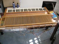 |
| In what is either the greatest lucky coincidence or a big scam, another organist who was reading this web site emailed me to let me know of an eBay auction of Reisner SAMs! Indeed, there was an auction of 40 SAMs that appear to be the correct tongue angle. Its also almost exactly the quantity I need. In addition, they look to be in much better shape than any of my SAMs, though they also date to the 1960s. It is possible they never made it into the kit that someone was building. I put in a bid. Someone actually bid against me! These are pretty obscure parts so I was quite surprised. However, I won the auction at much less than my upper bid limit. I have paid for the SAMs and I await their arrival. If these arrive and have the correct angle and work (or can be repaired) then I have enough to complete my console! |
 |
|
Saturday,November 7 2009 – Stop tabs and a test keyboard – and the very first notes (sort of)!
The company I chose to engrave the stop tabs was Arndt Organ Supply. I had read a lot of testimonials to the company on line and had gotten their catalog. I had not heard back from them for several days and my wife and I had gone to Sun Valley Idaho where I was performing in a large jazz festival. During the festival, Bob Arndt, the owner of the company, sent me a very nice email message. It turns out that he is also working on a large three manual theater organ for his own home and he is using the samples that I have chosen. He sent me a photo of his console under construction. It really makes a difference if you own a company that builds consoles! His is a work of art. In any case, he sent me his price list and I decided to have him build 82 of the 165 tabs I will need. The remaining 83 would come from the collection I obtained from Ken Rosen. I also ordered console tags from Arndt, the little labels that indicate the various divisions along the bolsters.
With the stop tabs under control, I turned my attention to the keyboards. I had originally planned to create long extension cables so that I could play the organ with a keyboard removed from the console. In this way I could adjust the contacts and action using sounds as my guide. Now I had a better idea. I used Craig's List (a suggestion from my son, Elliot) to find a very cheap 61-note MIDI keyboard for sale in my area. For $60 I purchased the Yamaha keyboard in this photo. It is almost new and works completely. |
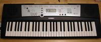 |
| The idea was to wire cables in parallel with the keys and so I can plug any of my organ keyboards into the Yamaha and use its tone generators and MIDI to hear when the contacts actually fire. I took the Yamaha apart and found how the keyboard was scanned and connected to the tone generator board. Unfortunately, the scan logic was such that a simple parallel wiring as I had planned would result in my external organ keyboards being able to play only six different notes! I could not play real music, but I could still do the testing and calibrating that I need. I soldered a wire at one end of each of the key contacts and one more to a circuit board with the scan logic. I had to drill a hole in a small circuit board for the latter. |
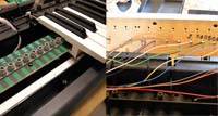 |
| The other end of the wires are connected to eight 8-bit ITW-Pancon MasCon connectors. These are the connectors that Classic Organ uses for the control computer - so these are the ones I will use for most of the console wiring. This was the first time I had attempted to connect wires to the MasCon system. It was very easy! The tool I had purchased for the job worked like a charm. This is much more pleasant than soldering - and probably a lot more reliable. |
 |
| Here is the Yamaha keyboard reassembled with the eight cables coming out of its side. It is ugly but very functional. In addition, I actually did this in a way that the Yamaha is still fully functional in its own right in case I need it for some gigs! |
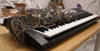 |
| I received the 82 stop tabs and various console tags from Bob Arndt soon after. Here is a photo of some of them. They are excellent and will make a huge difference in the look and playability of the organ. I carefully went through the order checking it for accuracy and discovered only a single text copying error in the entire bunch - quite a testimonial to Bob's company. In addition, he even corrected my spelling on two tabs! Otherwise, I would have had some "Castinets" and a "Libelich Flute!" |
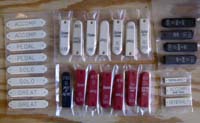 |
There was one problem, however. For whatever reason, Bob must have missed a diagram I sent that showed where the mounting holes should be drilled to match my existing stop tabs. In its absence, Bob used a standard location and it turned out the two were not the same. In the photo, I show one of my existing tabs (left) and one from Arndt (right) with the mounting holes lined up.
Bob and his company offered to replace all the tabs in the order. Rather than have him do this, we agreed that I would order the remaining 83 tabs so that they would all match completely. Bob even gave me a discount on the new order. Bob has demonstrated both a quality product and a high business ethic and I definitely recommend his company to others who are building or restoring organs. (I hear he is also a fine organist.) |
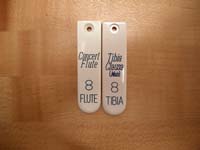 |
| On the evening of November 6,Karen and I assembled the various parts once more so we can see the overall progress. Of course, nothing plays - yet. I hope to remedy that soon. The tabs will all be replaced with the Arndt tabs after the final shipment arrives in a week or so. I also still need another ~35 SAMs to complete the top bolster. But overall, it looks great. I invited Ken Rosen over to see the progress Karen and I had made using his discarded console shell. Ken also spent a couple hours at my Rodgers playing the theater organ specification through jOrgan and Hauptwerk on the touchscreen. He gave it a thorough workout trying registrations in various organists styles. I think it passed the test. |
 |
| The next morning, Karen and I took the console apart once again. We moved the great manual to the workbench. I created a MasCon cable with the top five notes plus the common wire. I then attached it to the corresponding cable on the Yamaha test keyboard. We turned it on and it actually played! This counts as the first notes played by the console in this project - even though the keyboard was out of the console and the sound was a pretty bad grand piano patch. |
 |
| I wired the remainder of the great manual and tested all the contacts. One contact's feeder wire had been broken so I will have to repair it. The rest seams to work! There is defiantly some contact bounce and dirt issues. I will have to got through the contacts and clean them. However, this is a very major milestone as it shows that the keyboards can be made to work. |
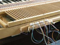 |
|
Monday,October 12 2009 – "Final" specification and tongue transplants
I developed a new specification for the organ using 30 of the 35 ranks in Neil's 3-35 sample package. Of course, no 1920's era theater organs with only three manuals had as many as 30 ranks, so I had to draw my inspiration from large organs, more modern rebuilds, and other electronic organs. I sent my draft specification to several theater organists that I know and respect. What ensued was a nice little debate over the relative importance of various stops. I made two changes based on the email responses and I updated the specification on this web site.
Here is the jOrgan console I created for the new specification. I got it working with my Rodgers to try things out. It sounds great and I have all the sounds I think I will want. It is very nice to have the larger scale solo tibia, the style "D" trumpet, the better piano, and the vibraphone. I also now have a nice 32' diaphone to anchor the pedal.
In the "what else can go wrong" department, the "5" divisional piston on my Rodgers popped out and I now need to schedule a service call! |
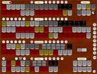 |
I had a great idea driving home from work one day. Ken had given me a small box of stop armatures without magnets. These are also Reisners and the tongues have the correct (steep) angle. Maybe I can transplant these tongues to some of the Reisner SAMs that have the shallow tongue angle? I used a small nail to hammer out the pin that holds in the two tongues. I then carefully moved the steep tongue to the SAM and hammers the pin back. It looked fine - but it did not move fine. Somehow, the act of removing and registering the pin created binding that caused the tongue to move with too much friction. |
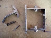 |
My solution was to go to Home Depot and buy a box of 1" #16 nails. I used these to make fresh pins for the tongues. I carefully bent the pointed end of each nail to keep the nails from falling out. The result looks a bit funky but truly works correctly.
Here you see a disassembled SAM awaiting the transplanted tongue. |
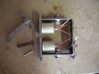 |
Here you see another photo in the tongue transplant process. It shows the nail installed as the replacement hinge pin. I now have 29 SAMs. I also can take the seven remaining steep angle SAMs and transplant their tongues too, assuming I decide that is easier than repairing them. This will give me 36 SAMs -one more than enough for half of the top bolster. At this point, I will be completely our of workable SAMs in both angles so I will need to find 34 more to complete the project - and probably a few spares for ones that actually do not work after final assembly.
I also sent a request for quote to a company for engraving stop tabs. I decided that, if this is not too expensive, I should do this while I have the bolsters on the workbench. As I wait for the response, I will be away most of the next two weeks playing jazz with the Nightbloomers. |
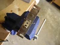 |
|
Monday, September 21 2009 – Back to the SAMs, lots of supplies arrive, and the organ grows in ranks!
After I successfully repaired 38 SAMs I was feeling pretty good. I rewarded myself by purchasing the next eight ranks in the KeyMedia Connaisuer series. In return, I had to make these additional ranks fit on my current design using 165 SAMs (25 on the straight rail and 70 on the two bolsters.) The new ranks included four I really wanted: a krumet, a musette, a second tibia, and a second vox humana.
As usual, I designed a touch screen control display to test my new specification. It is shown at the right. I used my Rodgers to test the new specification. The funny little half-size tabs are my solution to not having enough SAMs. I took a trick from George Wright and placed an "alternate traps" tab in both the accompaniment and pedal. Then each tab controlling traps actually controls two, depending on the position of this shift key tab. |
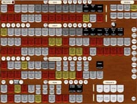 |
I am now going to be working a lot on the bolsters. Certainly it is good idea to take the bolsters out of the console and place them on a work bench. However, their odd shape makes this awkward. I had been doing this using a set of phone books to balance the bolster assembly. This would not do for the delicate SAM work I wanted to do now - using my precious repaired SAMs.
I bought a chop saw (I actually wanted to buy a new miter box, but the power saw cost only $50 more and the miter boxes I found looked rather flimsy) and its first use was to fabricate a bolster assembly stand. Here you see it, with the bolster assembly (minus the top rail) in place. I built it on a solid plywood base with felt feet so I can place it on a table. I also put two strong handles on the base so Karen and I could carry the bolsters between rooms. The stand holds everything in the correct orientation and gives me great access to the SAMs. |
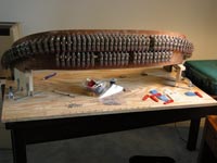 |
| While I was working on the bolster, the remainder of my hardware orders were delivered. Here you see bags of hundreds of solderless Mas-Con connectors that will form the ends of the cabling. There are several online electronic supply houses that sell these at very reasonable prices - with quantity discounts. |
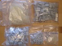 |
| Here some parts I ordered from Organ Supply Industries. I am very grateful to this comp.any for agreeing to sell me parts. They have been great to me. Here you see the parts I need to add second touch to the accompaniment keyboard. The springs are to the right. The felt punchings should extend the key screws enough to engage the springs. I'll get to this after working on the bolster for a while! |
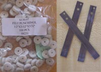 |
| Here is my sostenuto switch, also from Organ Supplies. It will be mounted on the leftmost expression pedal. |
 |
| My order of connectors included 200 small solder lugs. I am glad I had the foresight to order them as it has been so hard to find them in local stores. I need one for each SAM as shown. I stripped lengths of wires and soldered the lugs into a chain. I then screwed one on the bottom of each SAM. I have such a "bus" for each set of stop tabs, but no more than 15 in a row so as not to drop voltage too much. The lug on the end of each chain has a second hole so I can solder a feeder wire with -12 VDC. |
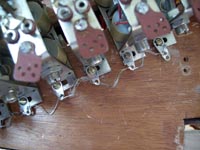 |
| Here is the straight rail and lower bolster completed. Some of the tabs have the wrong labels. I will add computer labels for them until I decide the specification is truly stable and order newly-engraved tabs. I had actually repaired enough SAMs to complete the first bolster and I have 17 more to begin the top one. That leaves me 53 short. If anyone reading this has some SAMs, please contact me and I'll arrange to purchase them from you! I have put feelers out on both the Hauptwerk and jOrgan fora. |
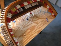 |
I played the 3-27 specification I designed using my Rodgers for a couple days and discovered a couple of minor deficiencies. In particular, the piano release samples were too abrupt and the vibraphone (which I really wanted to add) did not have controls for either the motor or the dampers. I emailed Neil Jensen and reported this. He responded very quickly and told me that he is working on an upgrade that will fix both of these. Then, one day later, he emailed me again saying he is sending me the 3-35 package (his complete organ samples) as a help to my project. The 3-35 organ has both of these corrected!
I was quite surprised and immediately emailed back by thanks to Neil. All I can say is that the samples have been top quality and Neil backs these with excellent response and service. All of this and he also plays a mean theater organ. Although I have not been to Australia in a number of years, I will definitely look him up on my next trip. |
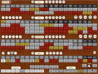 |
|
Monday, August 31 2009 – I do not like you, SAM I Am!
With the piston boards completed (albeit without any wiring - built that's the easy part) I turned my attentions back to the stop rails and those evil SAMs. Although I could order completely new Syndyne SAMs for this organ for just over $3,000, my wife thinks that's a bad idea. She wants me to have lots of fun spending lots of time on this project!
I have a box of correct-angle Reisner SAMs labeled "evil." The SAMs in this box do not work, for various reasons. However, the biggest problem seams to be magnet ground wires that have broken off from the armature. My previous attempts to simply solder the wires back to the armature failed because the armature is made of thick steel (it might be brass coated in something, I discovered later) and the magnet wires are very thin.
My new idea is to solder the broken wires to solder lugs. Finding solder lugs is a bit difficult since no one uses them anymore. However, I ordered a bunch online and found that Electronic City (a store in Burbank I frequented as a kid) is still in business and carries them.
Here you can see the ground wire from the left magnet soldered to a lug. This is still pretty delicate work. |
 |
I then drilled holes in the armature and fastened the lugs using small machine screws. I was careful to bend the lug so that the wiring would neither touch the moving parts of this SAM nor anything on the adjacent SAM after installation. The final step is a testing of both magnets using a test meter. I also test each of the switch contacts to be sure everything is working. The contacts are delicate and exposed - a poor combination. I know I'll have trouble with these later.
However, at least for now I have more good SAMs than I did yesterday! I have now repaired ten SAMs. |
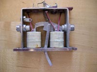 |
|
Saturday, August 22 2009 – Completing the piston boards
| I needed one more set of parts to complete the piston boards: colored screws. I had assembled the boards using regular steel screws from the local hardware superstore. After checking a few "real" stores, I located a place called "Best West Fasteners" about ten miles from home. I stopped there one day after work and handed them the steel machine screw. The man came back with about a thousand black versions in a minute or so. I told him I needed about 20 so he gave them to me free of charge! I will remember this store for an occasion when I need to really buy something. |
 |
| I needed to get the piston boards to sit closer to the keyboards. To do this, I took a hacksaw and cut down all the 1"x1" angles to about 3/4". It was a lot of work - but far easier than locating correct dimensioned parts! I also purchased some 3" tee-shaped mending plates. I cut off one of the tee parts to get an elongated "L" shape. I used these to attach the great and solo piston boards as shown here. |
 |
| Here is a photo showing all the piston boards mounted in the console. The keyboards are adjusted correctly, according to AGO standards including tilt. I then removed the piston boards and handed them to Karen. I left for a three-day trip to Washington DC. |
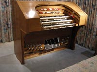 |
| While I was gone, Karen stained the piston boards. She got stain of the right color from Ken, who no longer had use for it. Karen carefully sanded the boards and applied two coats of stain, followed by two coats of shellac. The results look great. |
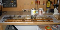 |
| Karen and I used the Klann piston insertion tool to set all the pistons into place on the boards. I then cut brown felt that Karen had purchased from a local craft store into 1/4" strips and fastened it to the bottoms of the boards. The felt came with a self adhesive backing and it seams to work fine for this purpose. If it falls off later, I can find better glue. |
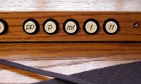 |
| Karen and I carefully reassembled the console and readjusted the keyboards. I added some angle brackets inside the console to fix the solo in the correct place. All the keyboards are now firmly attached and in the correct AGO configuration. The pistons look great. Of course, they do not do anything yet! Functionality is still to come. The console has a much more finished look now, however. |
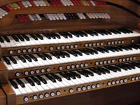 |
|
Friday, August 14 2009 – New Parts
| On Monday, August 10, I arrived home from work and discovered a small package at my front door. It was the shipment of parts from Klann. Somehow, they made $1000 worth of organ supplies fit in a box only 10" x 8" x 4"! One way they made this work was by a clever method of packing the 69 thumb pistons I had ordered as shown here. With these new parts, I could continue working on the console once again. |
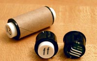 |
| In addition to the thumb pistons, I ordered eight new toe studs. These match the existing ones exactly. Also, like the existing toe studs, there are no wires attached! |
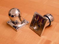 |
| The one oddball part I ordered from Klann was a potentiometer rack assembly for a swell shoe. Since the original Artisan organ had a mechanical crescendo mechanism, the crescendo pedal had no potentiometer. The Klann rack assembly was not a perfect match – but it was very close. I took it apart and reassembled the pieces on the existing bracket. This solution involved no welding – a very big plus for me. |
 |
| Here you can see the four swell shoes including the crescendo pedal (left most in this photo.) I once again went to my Rodgers organ to measure the vertical offset difference required for the crescendo pedal. I used scrap lumber from the piston boards to create a shim and then fixed all four shoes in place. |
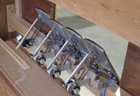 |
| This is what the console looks like as of now. Notice that I have doubled the number of toe studs. The ten to the left will control the pedal divisional combination action. The six to the right will be assigned to effects. Karen is now test staining the oak I used for the piston boards. Once it is stained, I can insert the pistons and mount them on the console. However, the great number of gigs I have this weekend, followed by another trip to Washington DC, will delay things a bit. |
 |
|
Monday, August3 2009 – A Piston Block
| While I waited patiently for the pistons, toe studs, and connectors to arrive, I switched my attention to fabricating the piston boards that would need to mount under each manual. As mentioned earlier, the console did not originally have a combination action. Hence, the key blocks had no indentations to allow pistons to be mounted. Instead, the wood simply came all the way out to where the board was mounted. The original boards (long since discarded) were simply screwed into the ends of the key blocks. When the console was modified to accept pistons, the entire width of the key block was gauged back about 3/4", just short of the key guide posts, to make room for pistons. Only a small amount to wood was left at either end of the keyboards for mounting the piston blocks. I decided that this would simply not provide a solid enough support and began thinking of other ways to mount the blocks to the keyboards. |
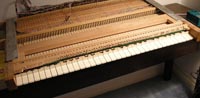 |
| I used my newly-purchased drill press to drill 3/4" holes for the pistons under the solo manual. I chose the solo as a test case because being the topmost manual it was easiest to remove from the console. The drill press worked like a charm and the holes were very well aligned. |
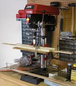 |
| I discovered that I could easily purchase 1 1/2" x 1/4" thick oak strips in three foot lengths since this was a standard size for oak floorboards. The wood matched the moulding I had already fabricated perfectly. I cut a length of this to slightly less than a keyboard width (33 1/4") and used angle hardware to connect it to the piston board. I used countersunk machine screws so that there were no protruding screw heads on either surface. For the moment I used stainless steel screws everywhere but I will replace the ones that show on the piston block with black anodized screws later on. These screws were just fine for this experiment. I also attached shorted lengths of floorboard to each end of this assembly to provide a mounting surface for the "box." |
 |
| Here you can see the "box" mounted to the underside of the solo manual. Notice that it attaches only on the bottoms of the key cheeks. I did this so as not to have to drill any holes in the key block and possibly damage the key guide posts. The resulting assembly is quite strong, owing to the L-shaped cross section. I also took the opportunity to adjust all the key heights on the solo manual at this time. There is still a touch problem in the center octave. I think it is a problem with the felts and I will look at this later. |
 |
| Here is a photo of the console with the solo piston block attached. If you look carefully, the key cheeks between the great and solo have a 1/4" (or even greater) gap. This is required in order to achieve AGO keyboard spacing. I will have to find a way to plug the gaps and make everything look right. This is a future task. Now I am off for another week of travel to Washington DC for my day job. Maybe the pistons will arrive before I return. My wife is supposed to locate a stain to use on the piston blocks before I return. |
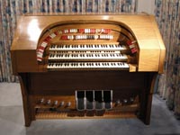 |
|
Friday, July 24 2009 – Big decisions and the beginning of real spending
One of the things that made this project seam affordable was that my friend Ken had boxes of used Stop Action Magnets (SAMs) that came from old instruments. I did not notice until several weeks into this project that these SAMs, though all manufactured by the same vendor (Reisner) came in two different styles. Look at the photo on the right. The angle at which the metal tongue protrudes from the armature comes in two different angles. Only the steeper angle works in my console! However, Ken's SAMs were divided about equally between these styles. There were only about 70 working SAMs in the steeper angle. I would have to buy more with the correct angle or figure out some way to use the other style in the console. Hence, it was finally time to contact organ supply companies and order parts. Up to this time I had spent alost no money on this project.
I did some Internet searching and talked to a few people. I idendified the companies that had the parts I would need. There were two: Klann Organ Supplies and Organ Supply Industries. I emailed both companies, explaining both my background and my project, and after a week I called them. Both companies were very nice to me. Although they do not normally sell to individuals (since we might undercut one of their regular clients) they understood my unique situation.
Organ Supply was the first to send me prices on items I would need to purchase. It was then that I had some sticker shock. Even at wholesale prices, the SAMs I needed would cost be close to $5,000! It was then that I decided I would have another look at using the gradual-angle SAMs! |
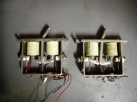 |
Here is what I have come up with so far. If I place a 0.5 cm shim (I used five small flat washers for the experiment) under the lower screw of the SAM, then the assembly is tilted forward enough to match the angle of the bottom tier SAMs with the steeper angles. The stop tab works fine in this configuration. I had to purchase some longer #4 screws for this, but that is fine. I'll need a lot more washers too. This tends, however, to push the top rail backward so I'll need to stiffen it with some intermediate supports.
This seamed to solve my problems – but when I began looking at how to fix some of the bad SAMs, I discovered a new problem.
As I searched for a way to resolder a magnet wire to the armature (which is used as the electrical ground) I noticed that the same ground was used for both the magnets and the stop swtich itself. From what I had read in the literature for the Classic control system, this would not work! Hence all of my SAMs may have to be replaced with more modern ones – and this would drive the price of the stops up to over $8,000!
I jotted down a circuit diagram of the SAM and sent it off to my friend Arthur at Classic. He responded quickly and explained that my SAMs would still work, as long as I sent Classic's -12V supply to the SAM's ground. I was very much releaved. |
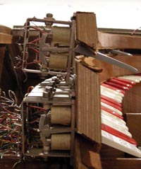 |
| I had also been doing a lot of thinking about the manual pistons. The console did not have a combinaton action so Ken had begun assembling piston boards for it. You can see in this photo of the keyboards (which also shows how nice the keyboards are) that Ken had used a drill to gauge out clearance for the pistons on the key blocks. He had gone as far as getting some moulding made and stained and placing some pistons into it. Of course, I want a different configuration of pistons. I also discovered that these mouldings were 1/4" to short for AGO standards – and they were a bit warped too! It was also clear that they could not be mounted with wood screws into the key blocks as there was not enough material left. |
 |
I looked on line and found several moudling stores around my town and began visiting them. It was just my luck that this very ordinary looking moudling (1/8" x 1 1/2" with one end rounded) was not at all standard! I finally purchased some oak door fillet moulding. Five pieces, each long enough to span a keyboard, cost only $17.50 and it was very strong. It was also a very high quality and would stain nicely. It was, hover, 1/4" too high! The salesman at the moulding store reccomended a cabinet shop nearby that could rip the moulding to my required dimentions. I went there immediately and the owner did this for me for free! I took his card as he is the exact kind of person I will need to refinish the console when I am done making everything work.
Here is the new moulding (upper) and the molding I acquired with the console (lower, and already drilled for pistons – but not in my configuraton.) I also purchased a drill press (another $110, but I'll have other uses for it) so I can drill the holes precisely.
I need to devise a method for mounting these too. My idea for now is to have 1/8" hardwood (maybe plywood) cut to abut to the bottoms of the piston mouldings and then attach to bottom of the key blocks. This should be very sturdy yet easily servicable. More on this later. |
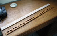 |
In the meantime, I received the price list from Klann. I can now order parts from both companies – and I'll need to since neither company has everything I need. I will order the pistons from Klann since they are less deep than the other brand and can use the same Mas-Con connectors as the rest of the console (no soldering.) I'll need 66 of these, so even at wholesale prices, this is a major purchase.
I just ordered the Mas-Con connectors and lots of other electrical parts from an online catalog. I included 200 solder lugs that I'll use with the mounting srews on the SAMs to create a terminal for afixing the -12V mentioned above.
I found a good supplier for the 26 AWG stranded wire I'll need for all the cabling. It is actually located about ten miles from home, so I will pick it up in person and save the shipping cost. I'll start with 200 feet each of ten different colors of wire – another major purchase. |
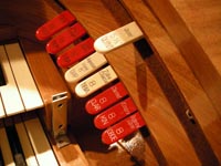 |
|
Sunday, July 9 2009 – Working with the keyboards
Since I had gone as far as I could with the stop tabs, I switched gears and worked for a few days on the keyboards. You could see from the first photo of the "moving day" that the keybaords were not mounted correctly in the console when I obtained it. I wanted to be sure the keybaords were securely mounted according to AGO specifications.
The first step was to do some surgery. Ken (or someone) had already done a few smart things with the keyboards. He had immobilized two of the contact bars on each and wired those contacts in parallel. This was good. Then he had created cables from the keyboards that merged in a large set of terminal boards. Unfortunately, this ended up making all three keyboards into one giant, heavy, and unwieldy assembly. I reluctantly cut the cables so that I could handle each keyboard seperately.I then removed the magnets that used to move the contact bars in and out of position. Since these were pipe chest magnets, I saved them to return to Ken for use on his pipe organ as spares.
One problem I noticed was that the keyckeeks were only 2.25" high. AGO specifications require 2.5". This was going to play havoc with the spacing between the keyboards and the placement of the piston rails. At this point, I had resigned myself to constructing completely new piston rails using narrower molding than the ones Ken had built.
Now that the keyboards were mich lighter, Karen and I placed them in the console. We shimmed them and ajusted their tilt (using set screws on the keycheeks as well as screws on the back end of the contact assemblies.) I walked back an forth from the bedroom to my living room, making measurements on my Rodgers organ and moving the theater organ keyboards until they matched.The photo shows the result. There are definlte spaces between the keycheek bolsters that will have to be filled with something. However, the good news is that the piston boards can actually remain full-height! The other bad news was that the keyboards were not held firmly in place by any of the mechanisms that already existed on the console. |
 |
The next step was to find a way to attach the keyboards securely so that they would not move or vibrate while being played. I started by removing all the keyboards once again. I attached the accompaniment keyboard (lowest) using flat el-shaped mending plates under the overhang. Four screws attached it to the plates, which are in turn attached to the console. These cannot be seen unless you descend to the floor and look upward.
The great (middle keyboared) was a much bigger challenge. I ended up using a pair of 90 degree angle plates fastened to the inner face of the second console key tier and in turn fastened to the sides of the great keycheeks. These screws take a bit of acrobatics to insert – and I will need to remove them many times in order to further modify and service the keyboard! However, when there were combined with a new placement of the bracket at the back of the contact assembly, the great was firmly in place. Karen and I placed the solo (top keyboard) in the console and shimmed it into place. This one should be easy to secure - but that will have to wait until next week after I return from playing at the Mammoth Lakes Jazz Festival.
Before we quit for the night, we replaced the stop bolster assembly and the console lid to make sure everything still fit together properly. We then attached pedal and brought over the bench - just to see how the completed project will look someday! |
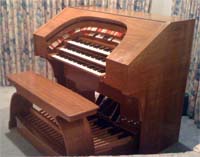 |
Here is a photo of me playing the dummy console and imagining that sounds might be eminating from it. |
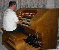 |
|
Sunday, July 5 2009 – Working with the used SAMs
I spent one night this last week examining the pedal contact assembly. This is contained in a wooden box that is about 6" high, 12" deep, and runs the entire width of the console. The pedals sit in front of this. When a pedal is depressed, it engages a crank on the front of this box. This, in turn, engages 16 separate switch contacts!In the original analog organ. A magnet would move each of 16 contact bars to allow the crank to close the corresponding set of contacts. I don't need that many- one will do. However, Ken had already thought of this. I looked into the box and someone (I assume it was Ken) had fastened three of the bars to they were always engaged. Then he wired the contacts for these in parallel. This should provide increased reliability. The only thing I had to do to the box was remove the old organ cabling (it was like removing a large tumor) and do some basic cleaning. The box now sits in the bottom of the organ console. I have not yet secured it in place. This will wait until I need to attach the pedal board.
When I acquired the console from Ken, I also took several boxes full of old "stop action magnets" (SAMs) that had been removed from this and other organs over the years. Some had stop tabs attached and others were empty. I also took several bags of stop tabs - although many of these were intended for pneumatic actions and I did not want to deal with modifying them to work with the SAMs. Ken also lent me an organ rectifier, which is simply a power supply that produces the voltage required to fire the two electromagnets on each SAM. One magnet flips the stop up and other flips it down. I used the rectifier to test the SAMs before installing them on the console.
I discovered that not all SAMs are alike. The company that makes these (Reisner) makes the metal protrusion to which the tabs are attached in two different angles. Only the steeper angle can be used on my console. Hence about half of Ken's SAMs (which he is selling to me at a LARGE discount since they are used) are useable.
You can see in the photo that I managed to find enough of the "steep angle" SAMs to populate the straight rail and about 2/3 of the lower horseshoe bolster. I will have to purchase more SAMs - the first major expense on my project. So far, the only money I have spent was $50 for the mover and about $50 to take my organist friends to lunch after the move! |
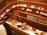 |
| Of course, it is too much to hope for that Ken's bag of stop tabs would have all the names I need for my specification. Actually, he had about 80% of the correct names - or ones that were close enough to use without any concern (I can use "Chinese Block" just as well as "Oriental Block"!) It is traditional to use a Dimo labeler to create the name changes on the stop tabs. When you visit pipe installations you see a lot of this. However, a Mac and a good color printer enabled a much better solution. I found two fonts that closely match the ones used by Wurlitzer on their stop tabs, color matched the specific tab colors, and printer labels to place over the tabs. Here you can see several of my labels on the straight rail. This system will do very nicely until I decide to have new tabs engraved later. |
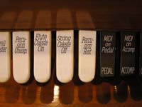 |
Here is a view of the back of the bolster assembly showing the SAMs mounted and lots of random wire hanging loose. I plan to mount terminal strips on the bolsters for collecting the wires and then use some sort of removable connector to pass the cables into the guts of the console. This will wait until I have purchased and mounted the remaining SAMs.
The screws on the top of each SAM (as well as corresponding ones on the bottom) are used to control the throw of the stop tabs. The idea is to adjust these so that the tabs all line up in both their "on" and "off" positions. I have done this for the straight rail. Only the "on" positions are adjusted on the bolster so far. I will wait until the next time I move this assembly to a workbench to adjust the bottom screws.
Since the original organ using this console was smaller, I have had to drill new holes for mounting more SAMs. There will be 71 SAMs on each horseshoe bolster when I am done. |
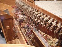 |
| Ken did not have enough SAMs for me - but he had plenty of stop taps. I have laid out the remaining tabs on a long table, backing them with 1.5" tape to hold them in sequence. Only about 20 of these need my new labels - but they all need new SAMs! I visited two of local hardware stores today to purchase some stuff. I bought lots more screws for mounting SAMs. I also bought some "mending plates". These are flat metal plates, 3" x 1/2", with holes through them. I will use these to both reinforce the bolsters and to mount separators between the organ's divisions. I also bought contact cleaning spray to begin working on the keyboards. |
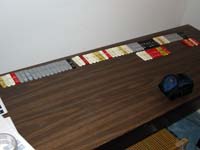 |
| Here is an overview of the console after one week in my possession. There is a lot of work left! |
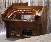 |
|
Sunday, June 28 2009 – Moving Day
| Here is what the console looked like sitting in Ken's studio that morning. You can just make out the shutters from his solo chamber to the left of the console. Ken had hoped to use the console to expand his pipe organ. He and a friend had done some work already. The stop tabs had all been removed. Ken had handed me boxes of stop action magnets (SAMs) a week earlier as well as tons of engraved Wurlitzer style stop tabs. The pedal board and music rack were lying elsewhere in the room. The keyboards are in the console – but not mounted correctly. A couple other organ friends showed up to help with the move. We took several of the smaller pieces (the bench, pedal contact assembly, music rack, piston rails, and lots of cables) to my car. The mover arrived at 10:00 and we began the arduous trip to my house. |
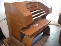 |
| Here you see the condole coming out of Ken's organ studio. The woman is the mover's wife. They pushed the console through Ken's pool area to reach a gate in back of his house. It would not fit through the gate. Ken had a wider gate by the side of his house, on a steeply sloped stretch of lawn. This is how the organ got here in the first place – but it was downhill then and uphill now. Six of us pushed and balanced the console on its dolly to get it through the wide gate. |
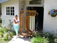 |
| Here the console has been loaded (with brute strength) into the mover's truck for the short ride to my house. The pedal board is behind the console. Karen drove my car back home with the smaller pieces and I rode with the mover. He stood in the truck bed to steady the load while his wife drove. |
 |
| We arrived safely and took the console off the truck. We removed the keyboards to make the console as small as we could. After the experience at Ken's gate, I was getting doubtful we could get this thing into its intended room. In fact, after bringing it successfully through our front door, we just could not make the turn through the 32" bedroom door to place it in the new lab. We started thinking of ways to take the console apart further – but I gave up after a few applications of a hammer and chisel. Whoever had assembled this organ kit long ago had been a master with glue and fasteners! It was time for an executive decision and "plan B." Karen agreed to let the console sit in our master bedroom during its refurbishment. In return, she will get the other bedroom as a sewing room. We took the console back out through the front door, around the house, and into the master through a large French door. Here you see the console sitting next to our bed. It will remain here for some time! Notice that I have already test-fitted the four expression pedals. The left three have working potentiometers. The fourth has none as it used to have a crescendo mechanism - now missing. I will have to outfit this with a potentiometer later. |
 |
| We placed the keyboards, temporarily, in the newly renamed sewing room. There are more key contacts than I have ever seen on an organ. I will have a lot of work to do removing the old cabling and accessing a few of the contacts. I also want to convert the Accompaniment keyboard to second touch. This should be possible. These are actually very nice wood core keys and well worth preserving. |
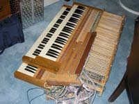 |
| Since I had the SAMs (stop tabs and magnets) for a week already, I had begun sorting them to see what I would still need to buy to fill out the bolsters. Karen came up with the idea of using an old hamster maze kit to hold the SAMs in groups of three in order. After the SAMs get tested and mounted on the console, this table (now in the sewing room) will move to the master bedroom to serve as my workbench. For now, I will use the kitchen table and a bench I have in the garage. |
 |
|
| |
|